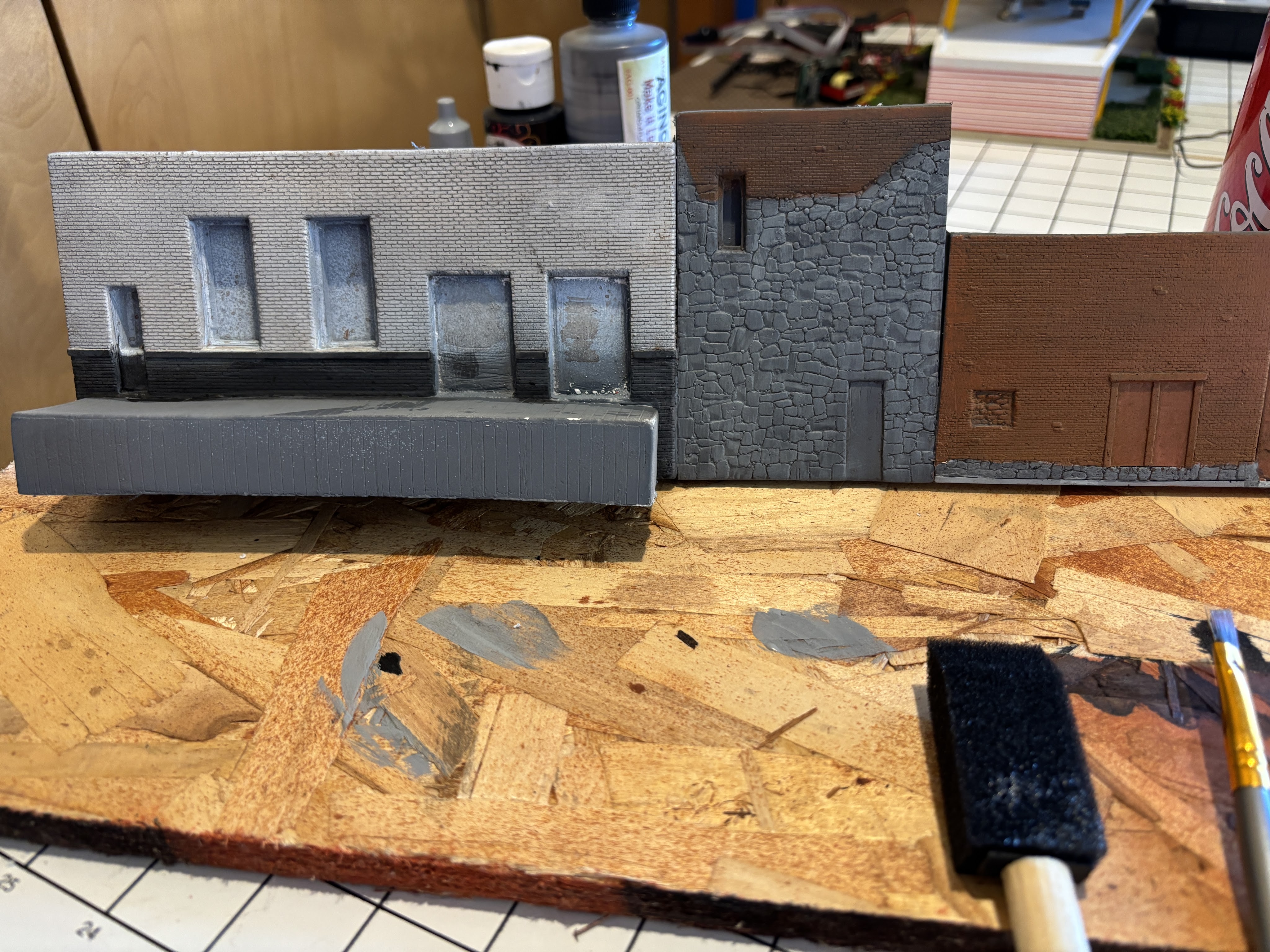
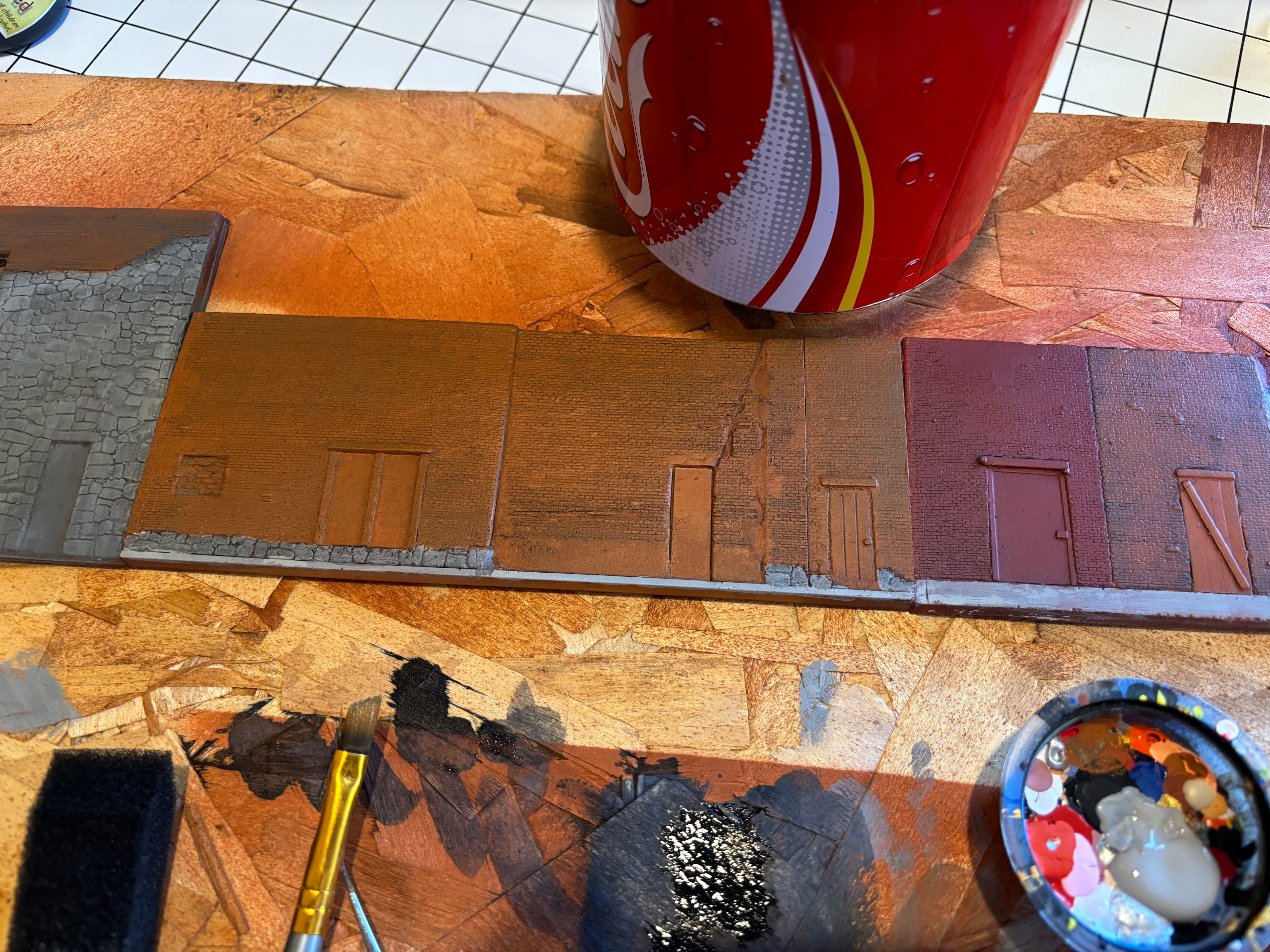
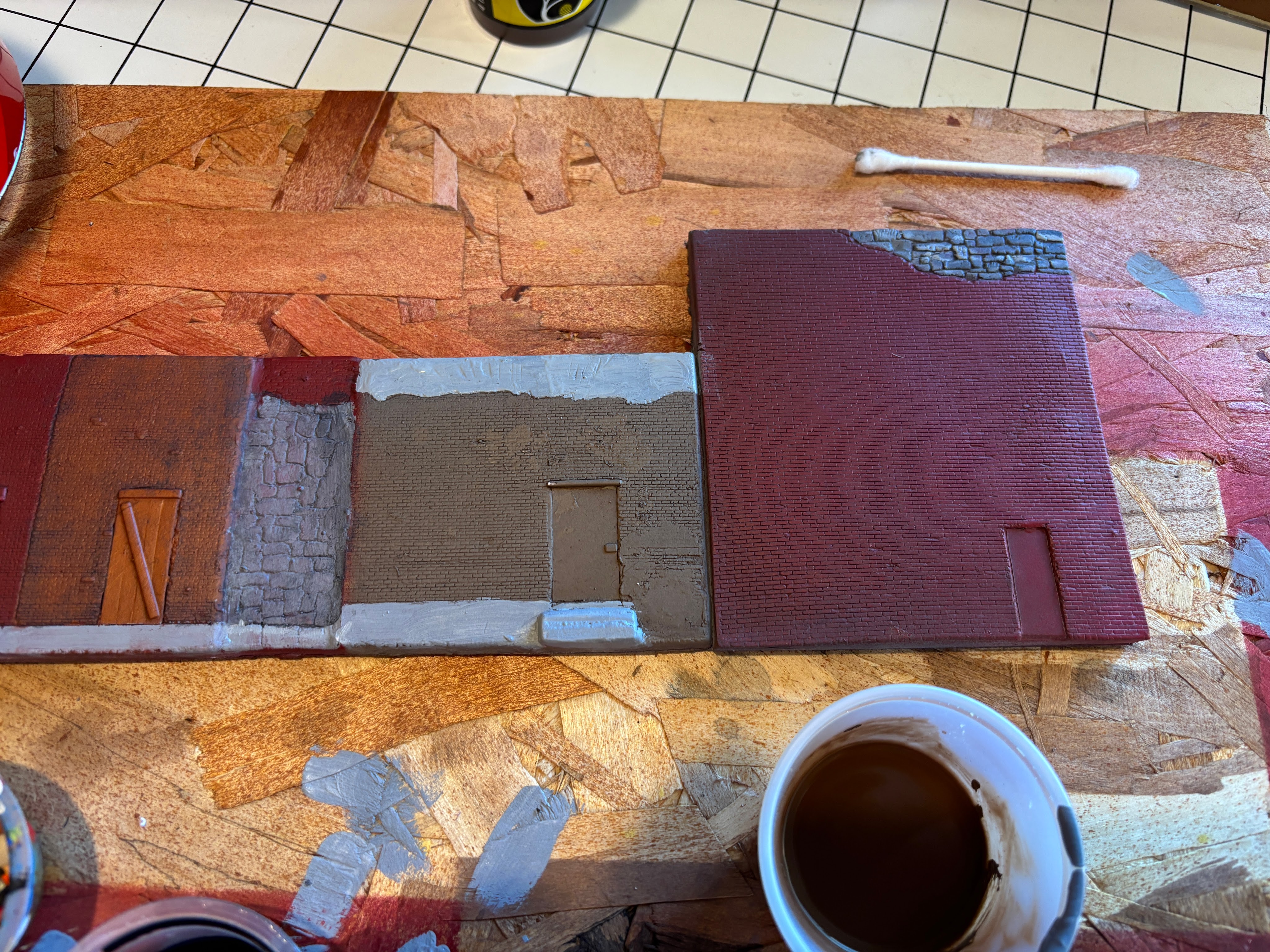
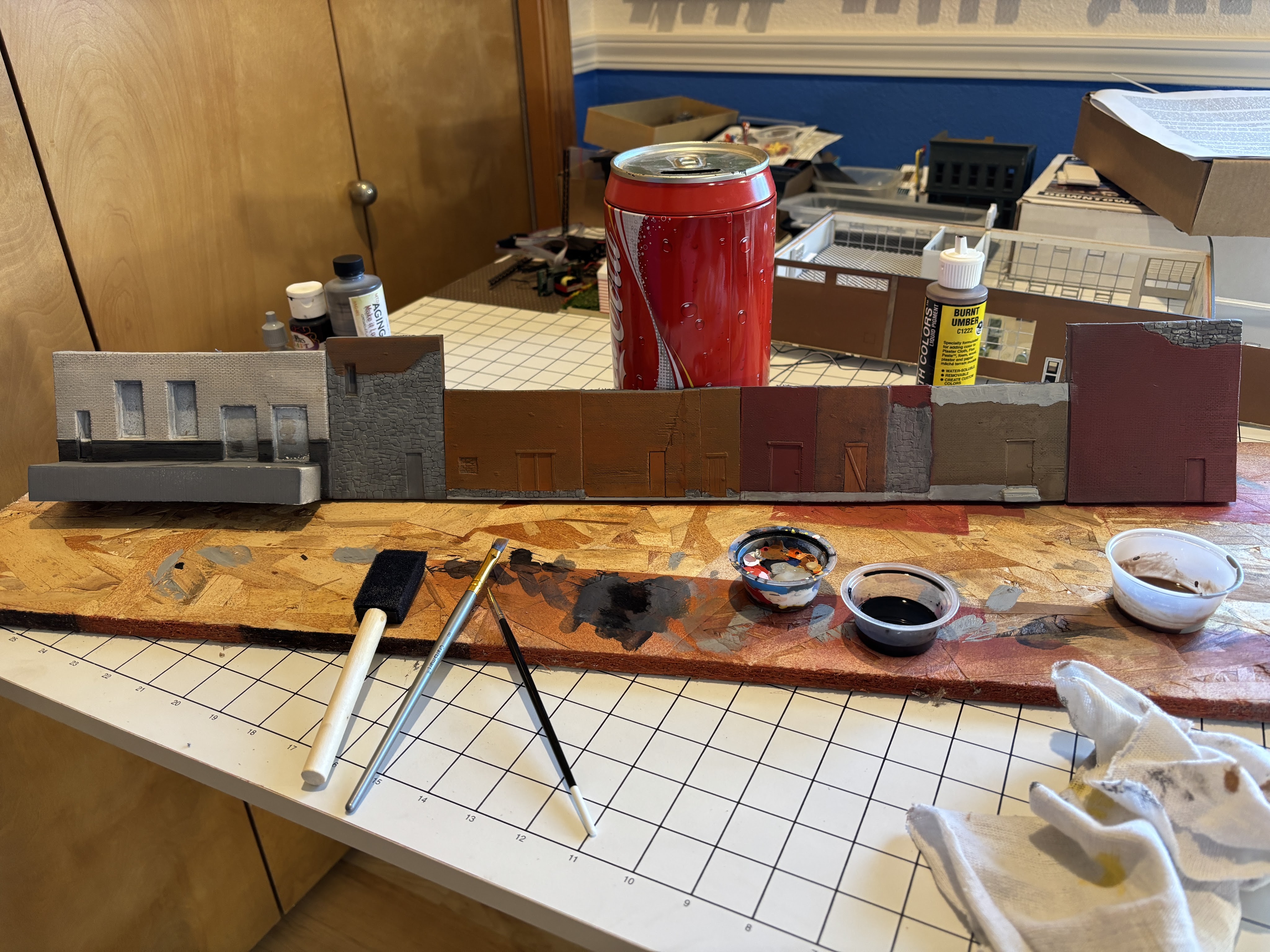
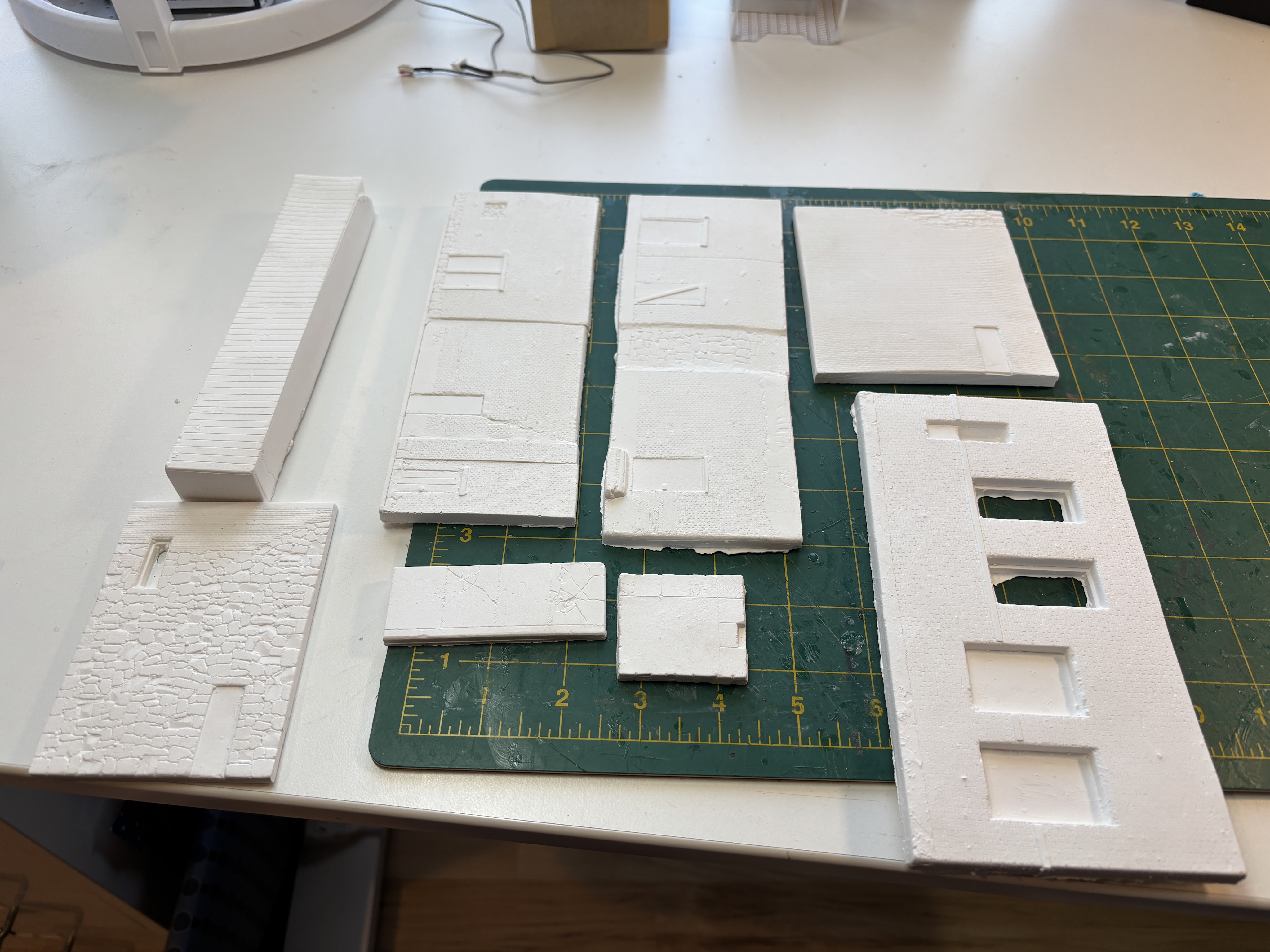
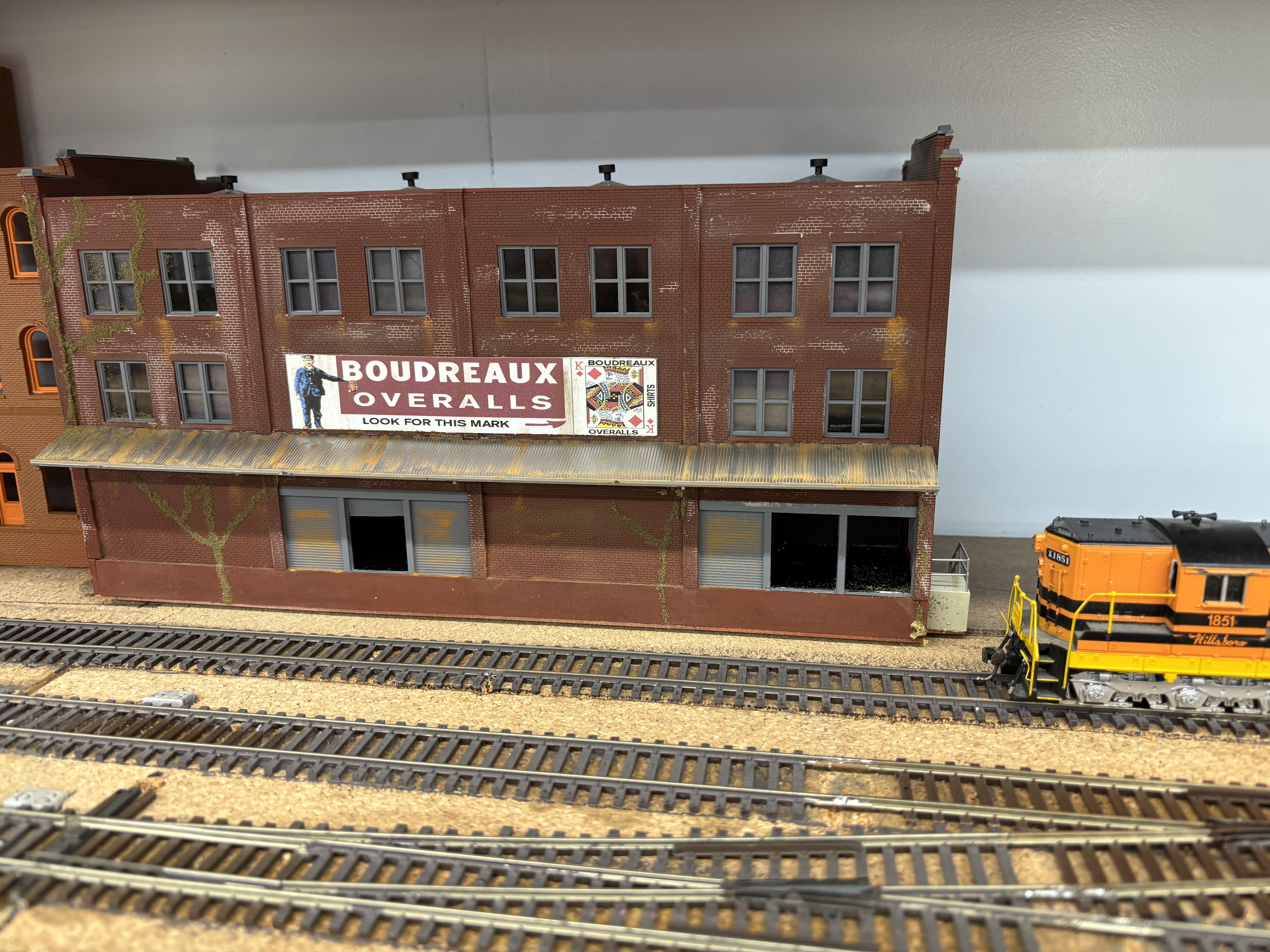
Last time we left off with painted walls. Since then, I painted some of the details, applied several washed of India Ink, and touched up some of the exposed stone with some highlight paint colors.
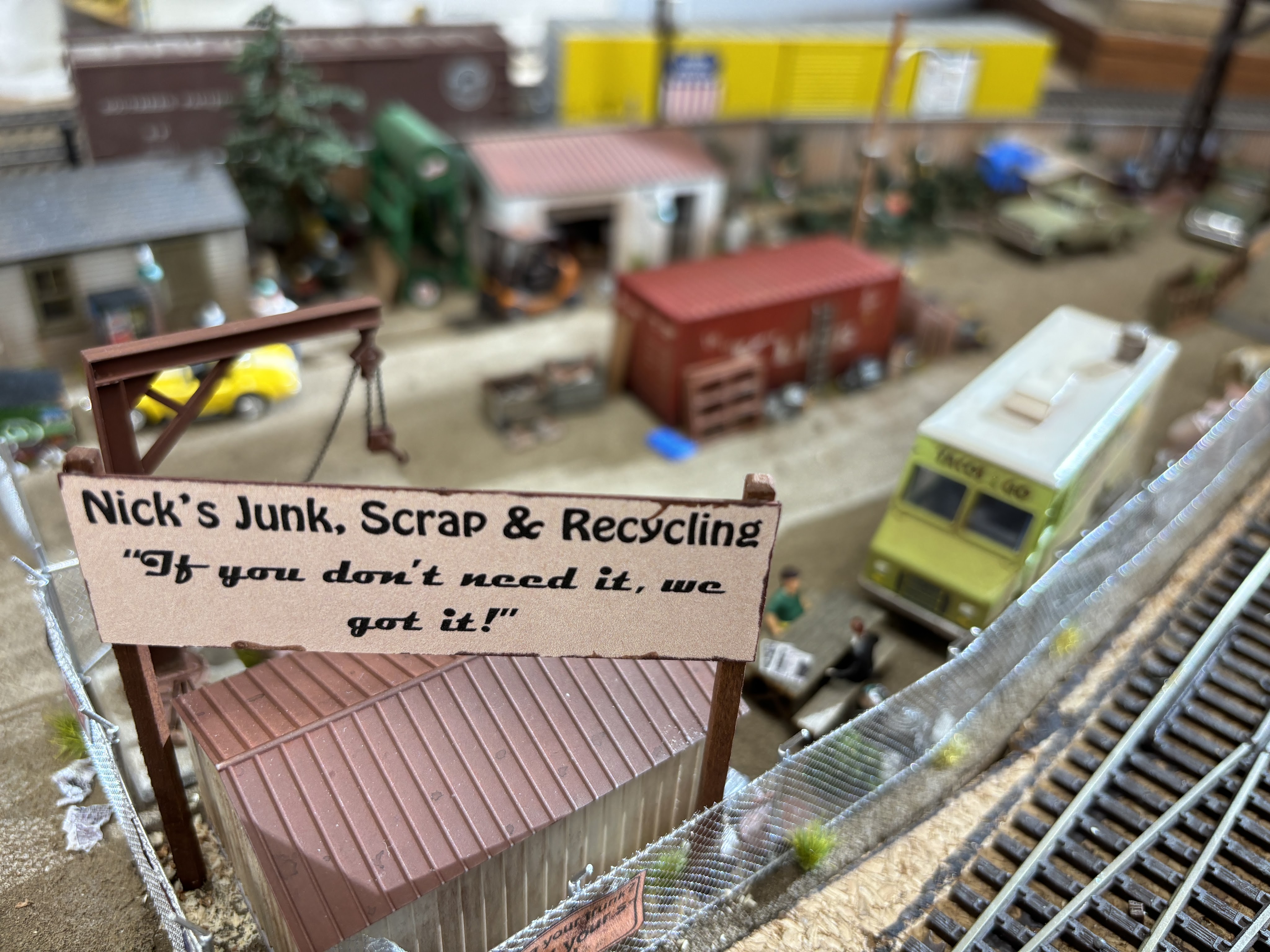
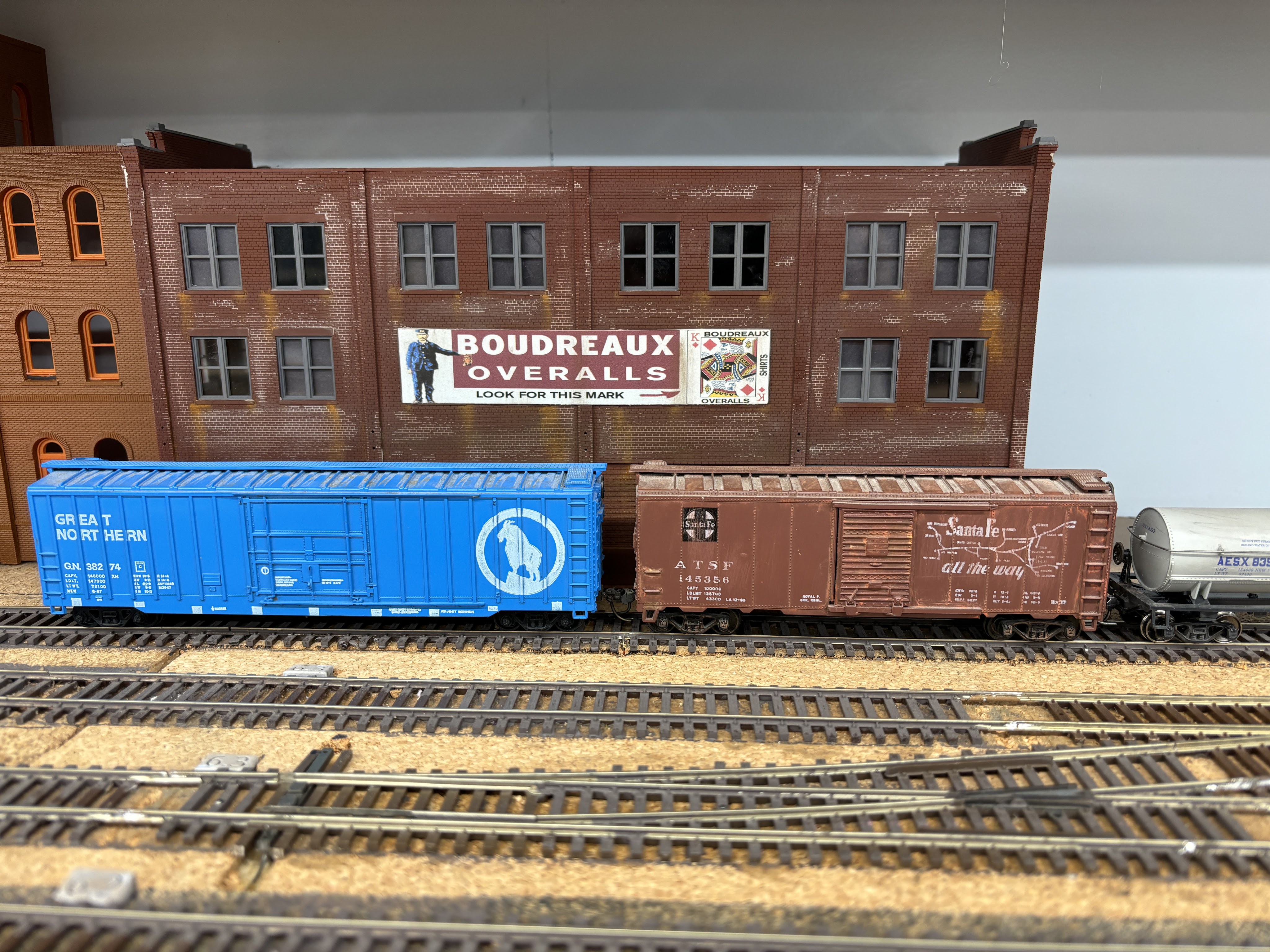
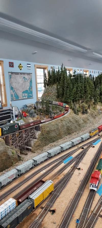
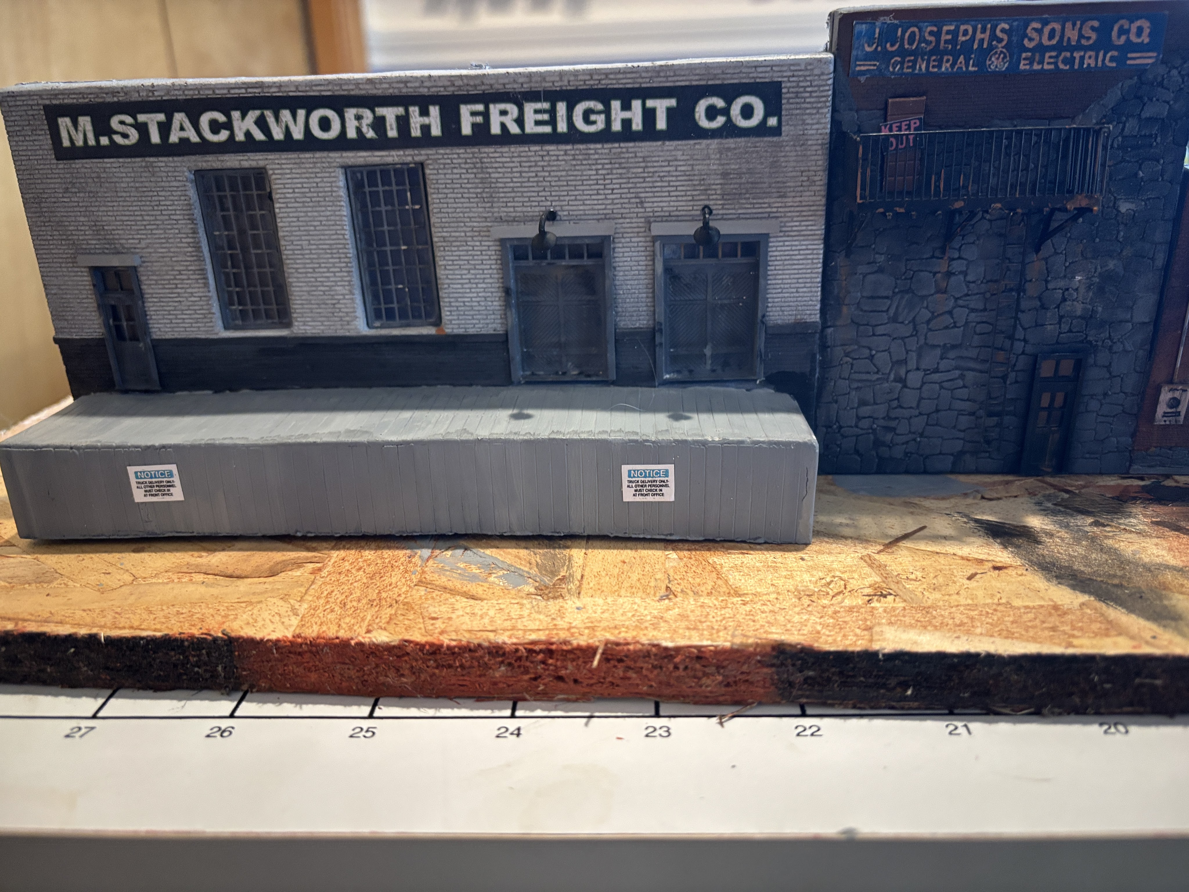
Once the walls looked good, I cut out the signs provided by the kit, applied them with white glue, burnished them into the brick and wall cracks, then gave them some light weathering using some paints and dry brushing.
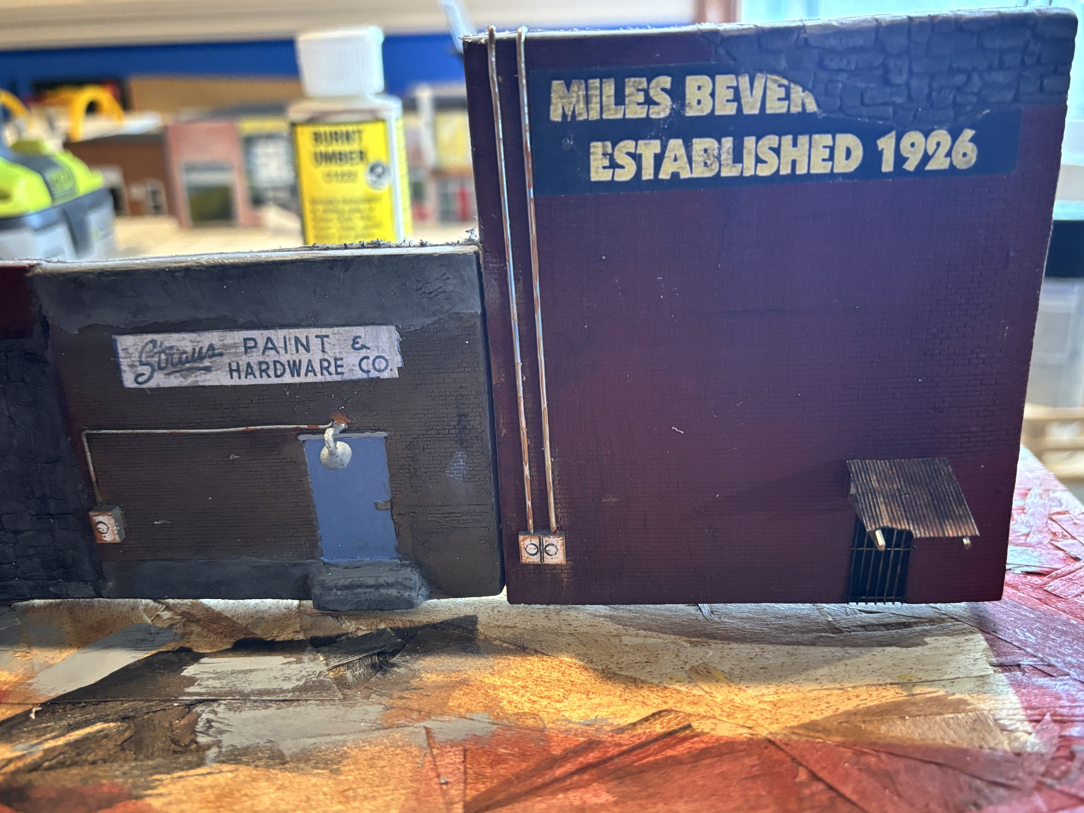
My next step was to add the detail parts: electrical boxes and conduit, security bars on some of the doors and windows, a couple of door awnings, a fire escape, and a few Woodland Scenics door lights.
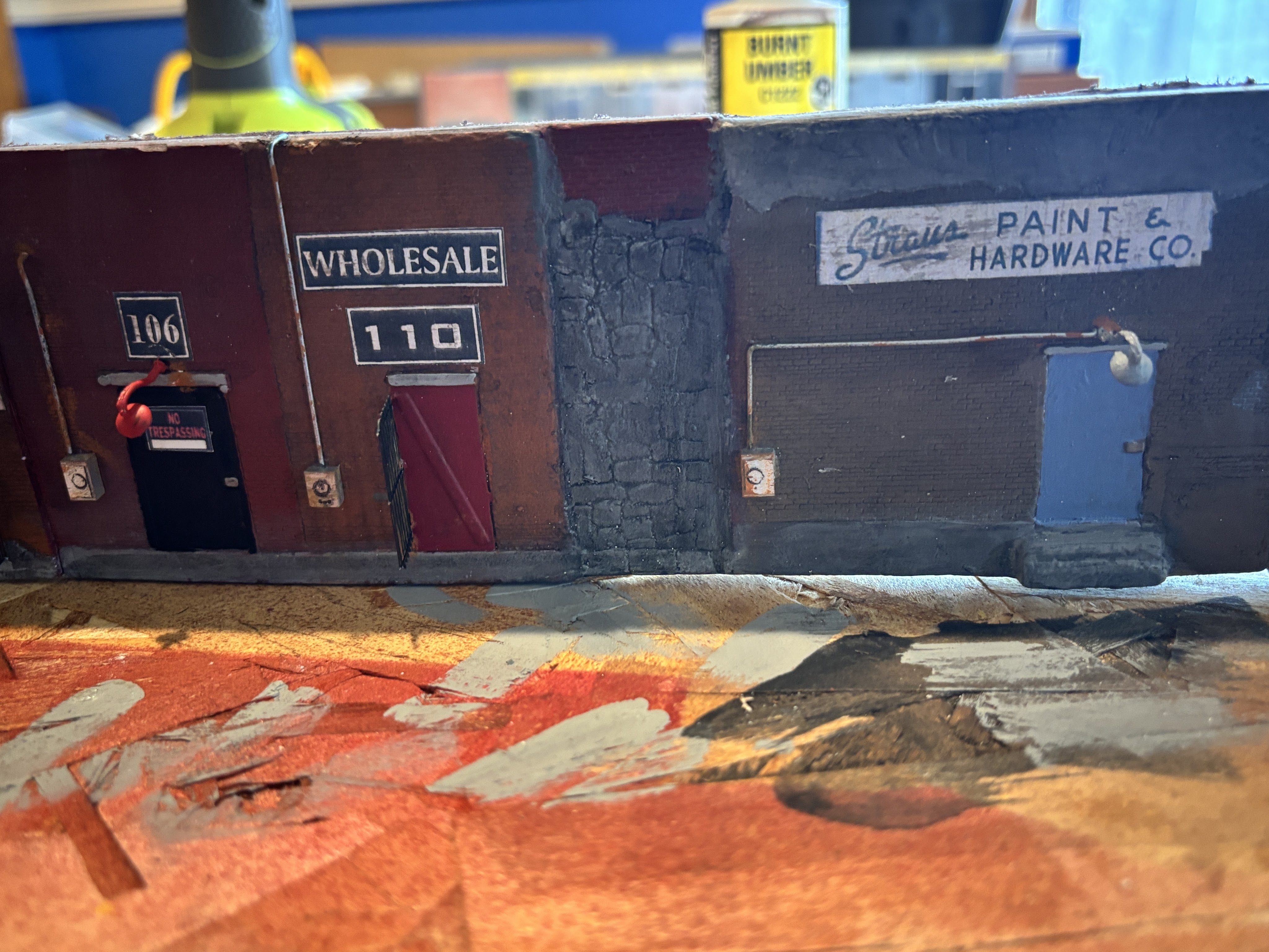
After all of these details were added, I went back and touched up some spots with more weathering – applied with paint and dry brushing. Hint: Weathering buildings goes a long way towards hiding any inconsisitencies, glue spots and other mistakes made during the building process.
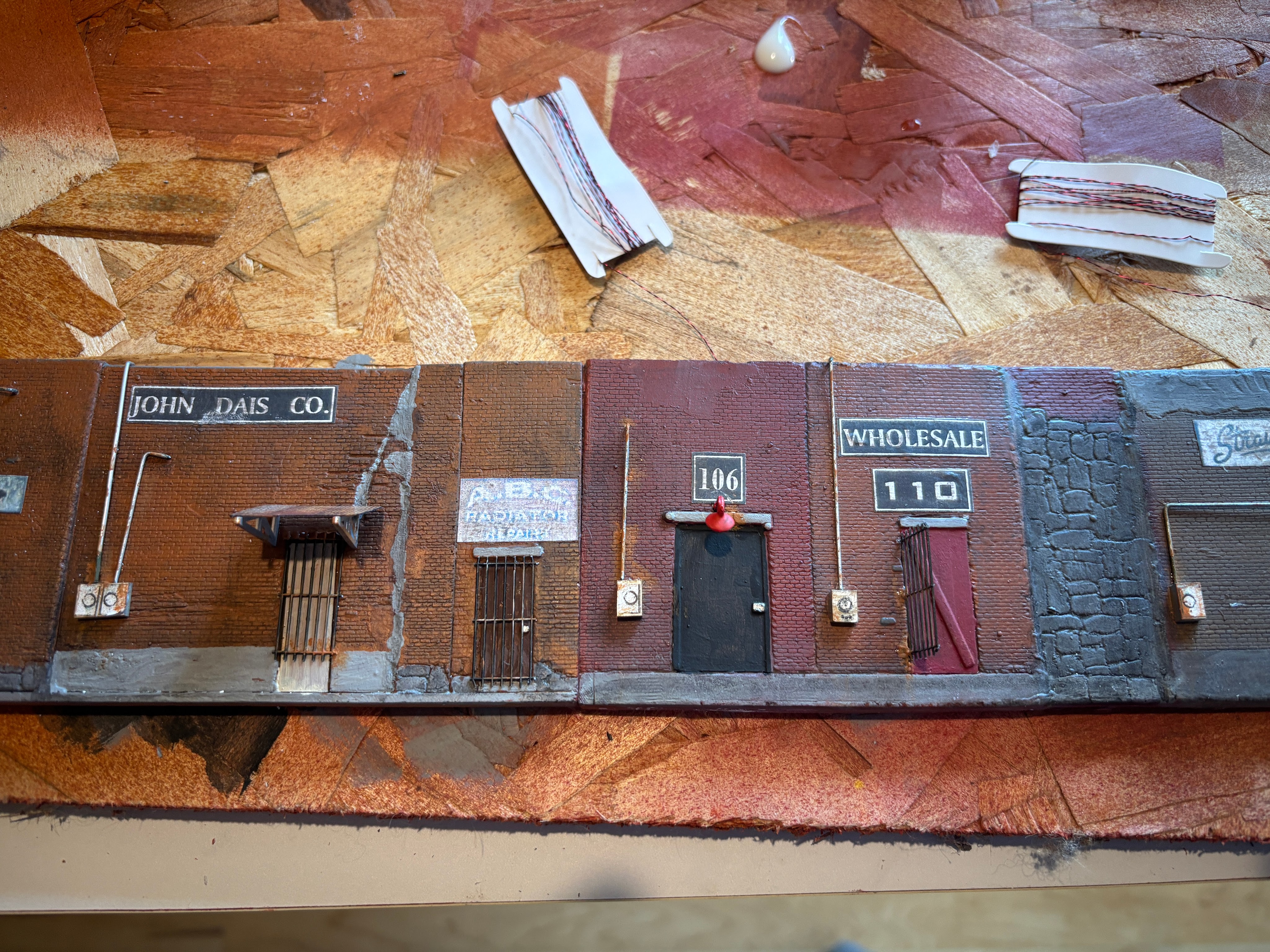
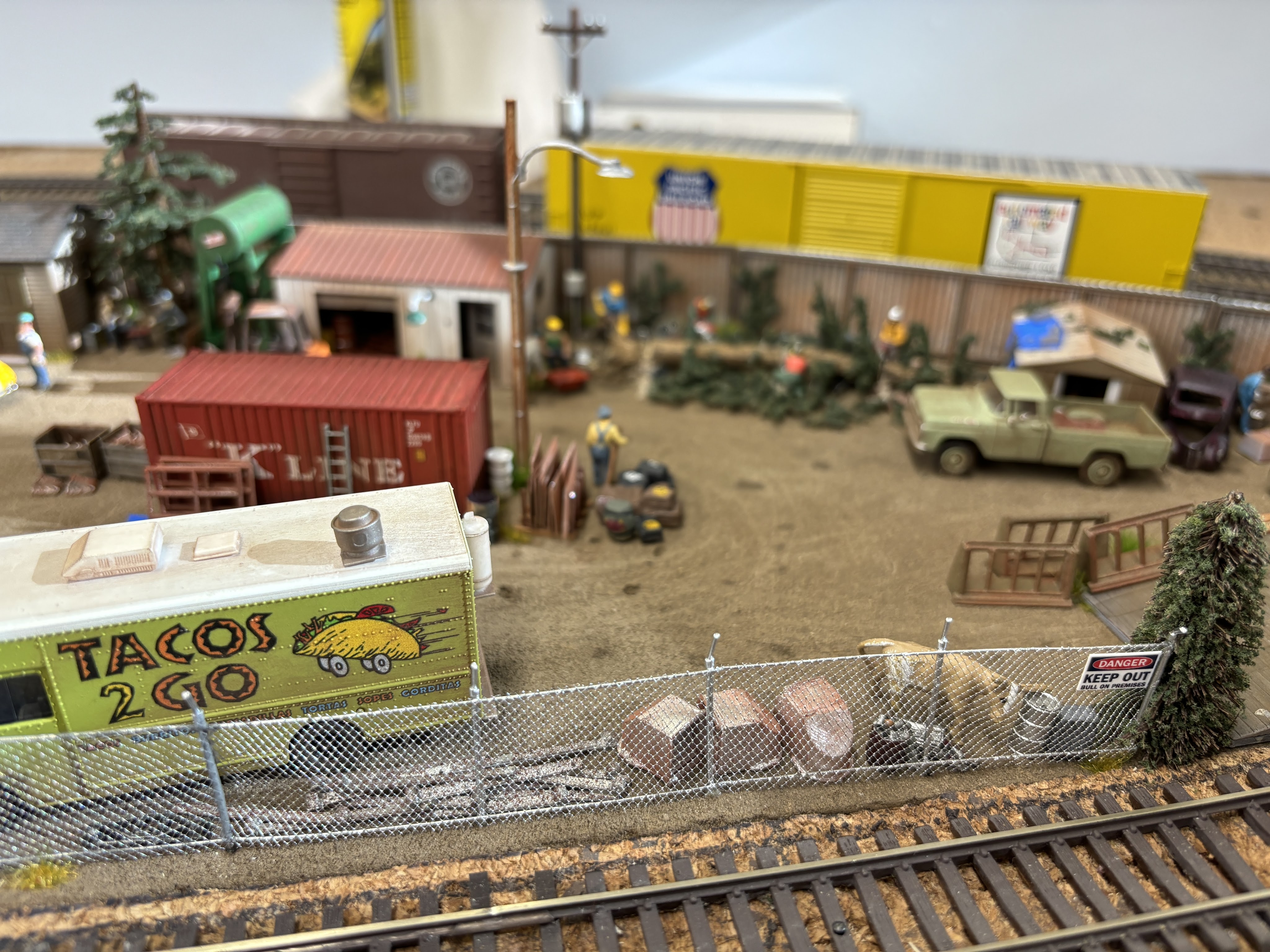
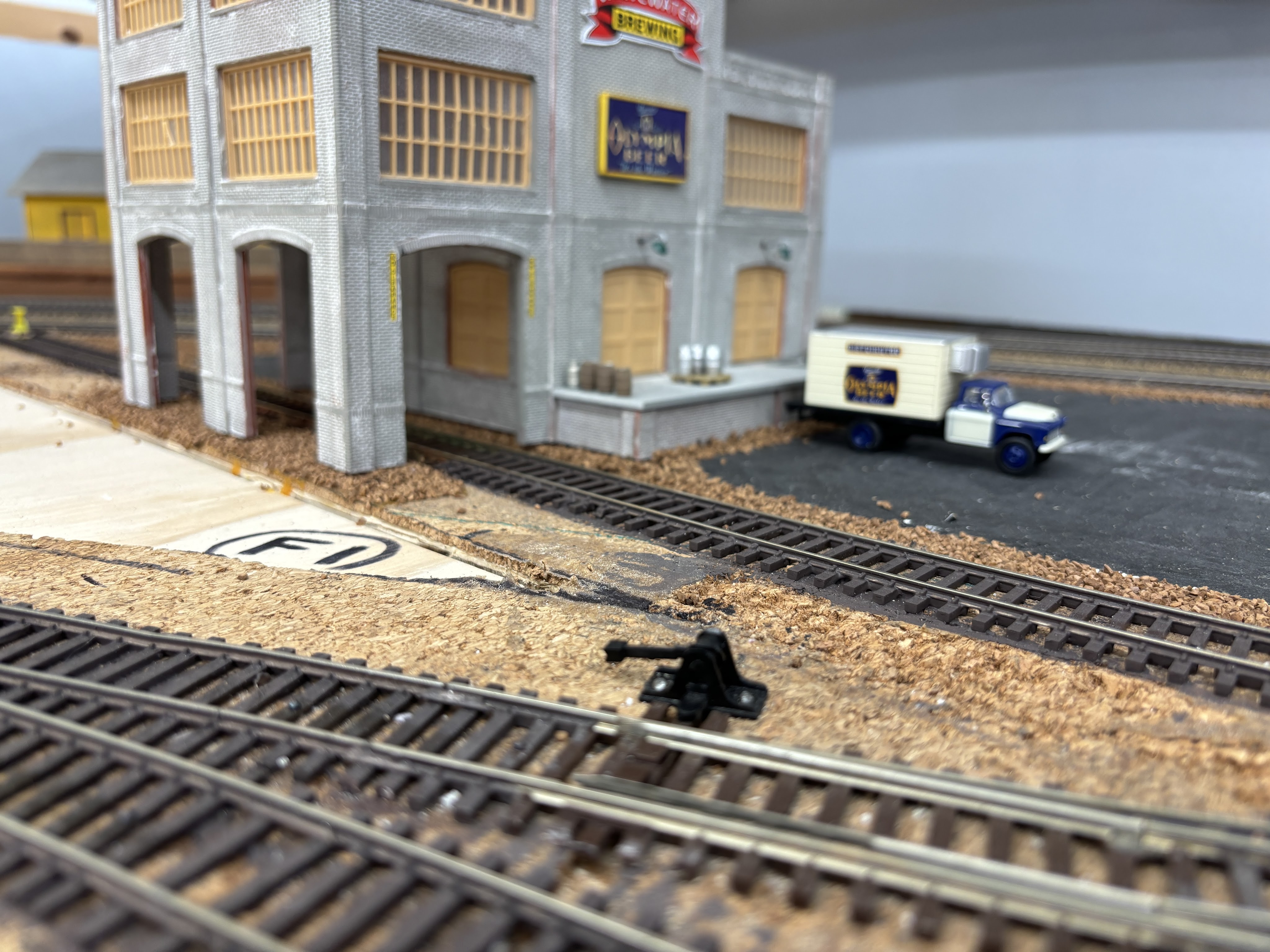
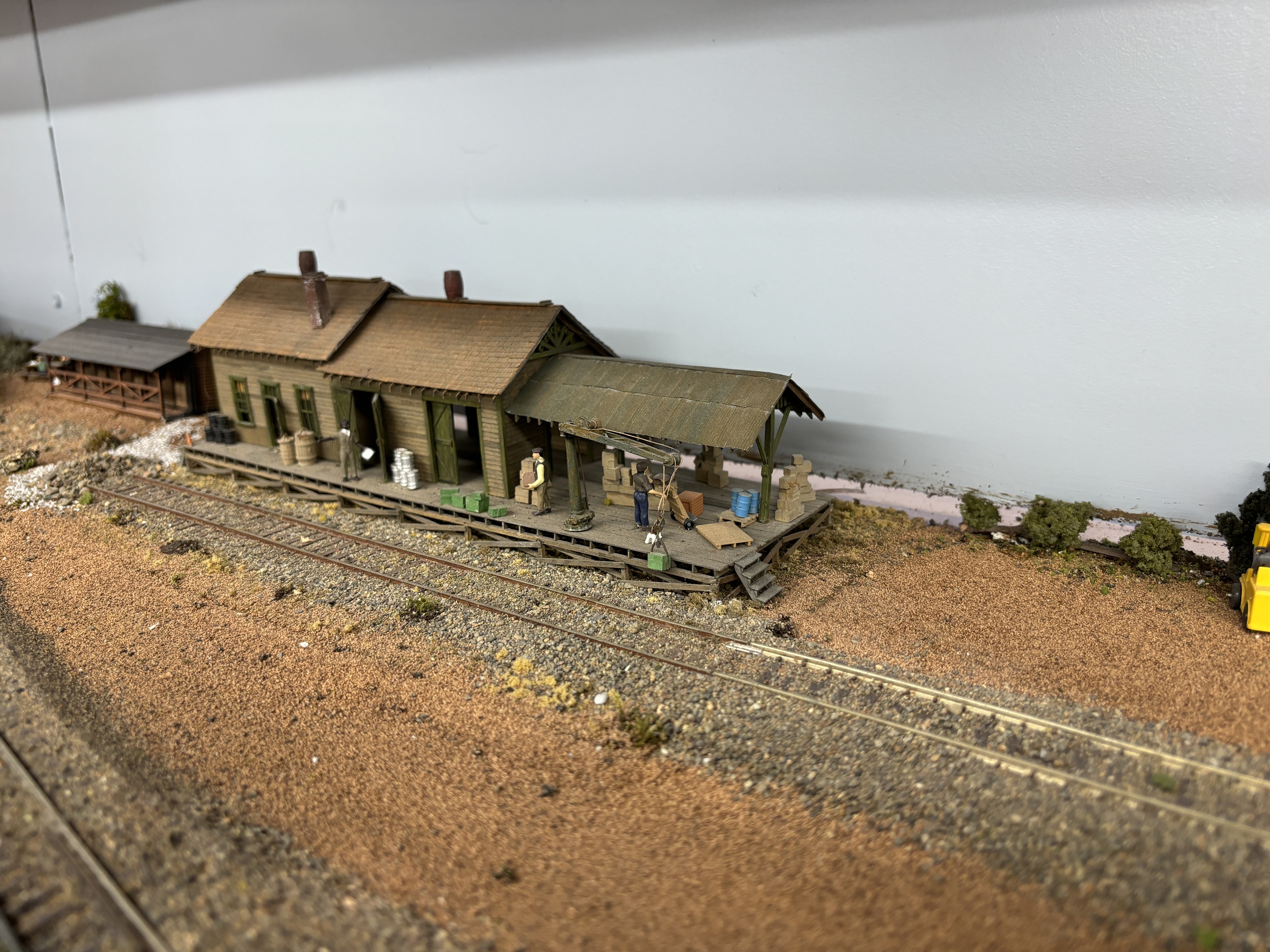
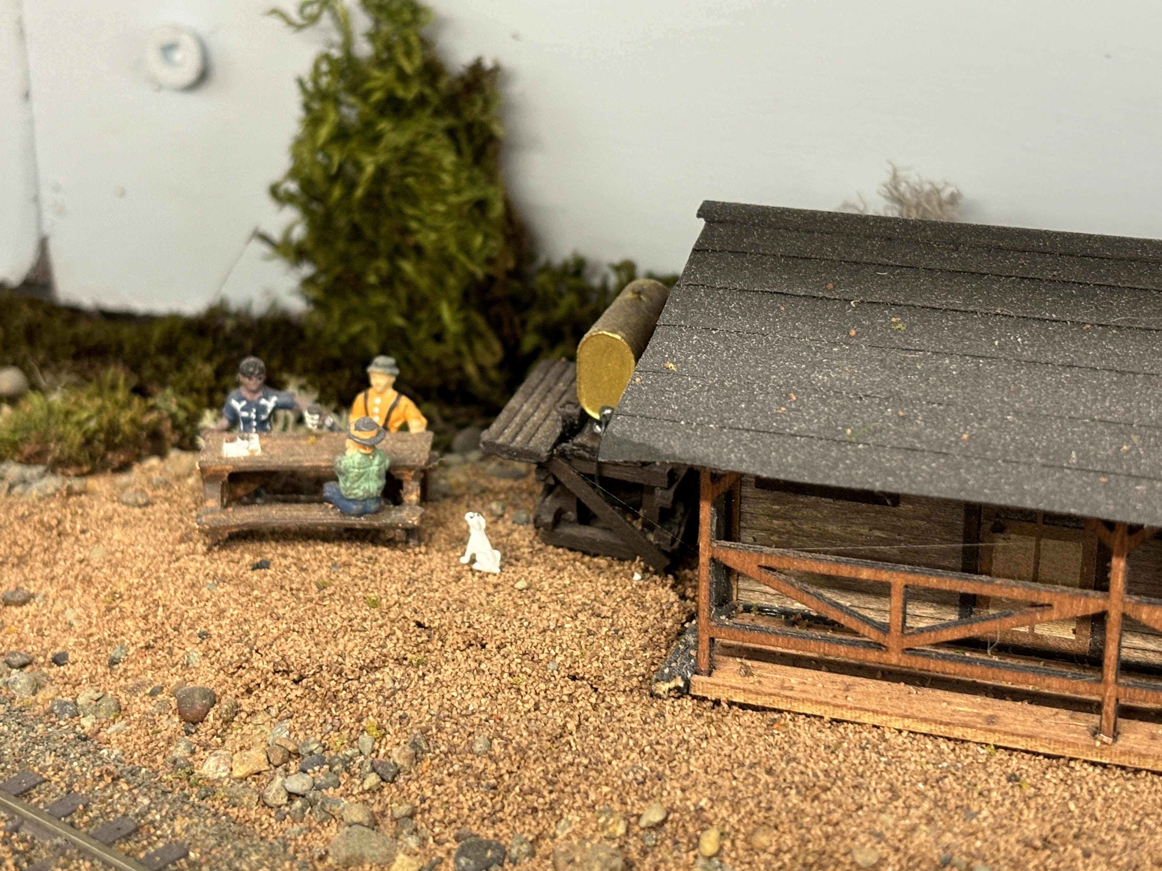
That is all for this update. In our final installment, I will show you how the backdrop building is installed on the layout and all the details that will be added to the scene: barrels, crates, boxes, trash, trucks, people and more.