Corvallis Society of Model Engineers
An HO scale model railroading club founded in 1959 and located in Adair Village, Oregon
4/24/21
The last report was quite technical and there were more colorful developments this week in addition to DCC documentation. One of these included a major step in helix construction. George has worked diligently for several weeks to wrap a fascia around the lower frame of this part of the layout. This fascia wrap created a tunnel almost 15 feet long and covered up Larry’s hard work on the rock liner. George’s framing included uprights to support outside edges of the subroadbed. On the lower level these uprights also provided a router guide allowing us to use a laminate bit to route out windows. These windows can be used for viewing trains inside the tunnel and good access to the tunnel interior.


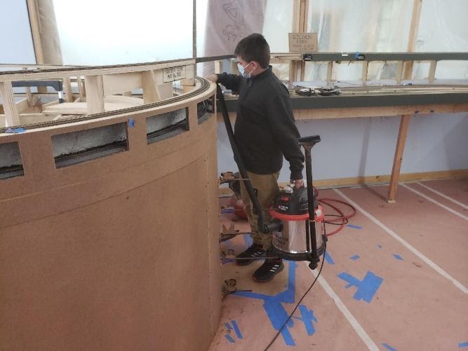
We had a sneak work session to rout out these windows. Larry and I did this on Saturday because we knew it would be extremely dusty and noisy. Gabe, a 6th grader from Redmond, Oregon came by to visit. Larry was cleaning up from the routing job and he drafted Gabe into running the “suckulator”. Even though we put him right to work, Gabe said he wanted to come by again.
Not only has great progress been made on the south helix but also our drive-in movie has found a home. With great frustration and challenge, Doug successfully modified existing framing in Corvallis to fit the theater module into a corner. We’ve been concerned about how we might locate this icon. For those of you who don’t know, this diorama was made by member Lyle Friese who has since passed on. The featured film, 3:10 To Yuma, was the movie playing when Lyle took his wife on their first date.
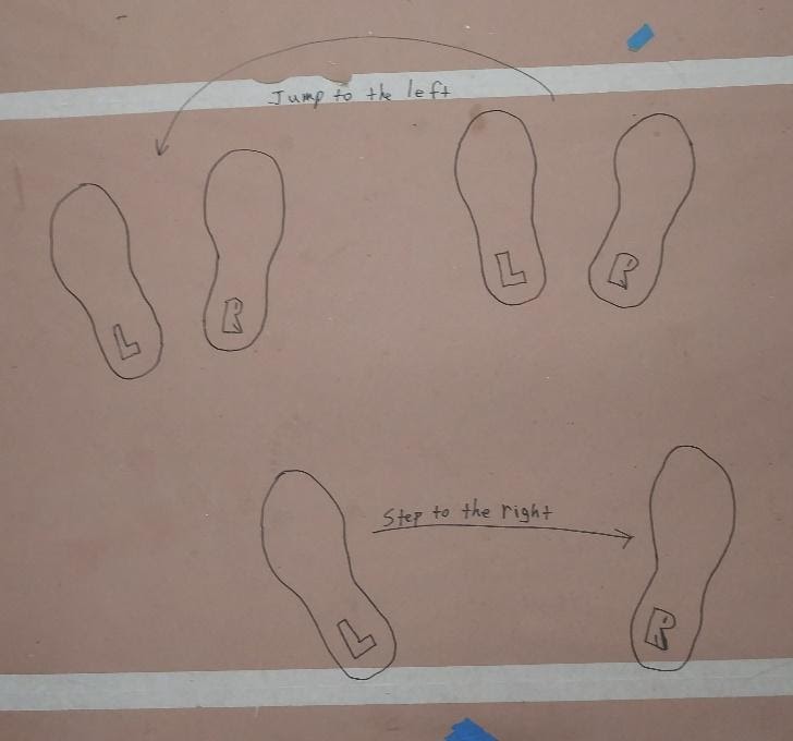
We have mystery dance steps with directions appearing on the floor between George’s Gorge and Eagle Point. It may be that CSME is the first model railroad club in America to have foot placement dance diagrams affixed to the floor complete with labels for “L” and “R” feet. During lunch this week a lively discussion developed about who the author of this artwork might be. Doug quickly defended himself against any allegations advising all present that it wasn’t him because he couldn’t spell “L” or “R”. Current evidence points to Lonnie.
Hopefully this progress report reads a bit easier than the last one and provides some exoneration for the infliction of such a highly technical document upon the membership.
4/21/21
CSME members who are interested in DCC documentation for our layout can review this narrative. It is NOT a requirement to run on the layout, however, if there are problems, it can often help to define exact locations to assist in troubleshooting. This is written as the DCC wiring system is being designed and as of revision 4/21/21. Names and wiring assignments may change but we will try to keep documentation up to date.
Here is a very simplified explanation of our DCC system. It has, among other components, the basic parts as shown in figure 1. We have a DCC command station that gets radio signals from our hand held throttles, processes them and sends commands to our 11 boosters. These boosters send information through (up to) 4 circuit breakers to sections of track called power districts. This information tells our trains to puff, toot, ding, back up, and go slow or fast. But how do we make sense out of all this stuff as it relates to our layout?
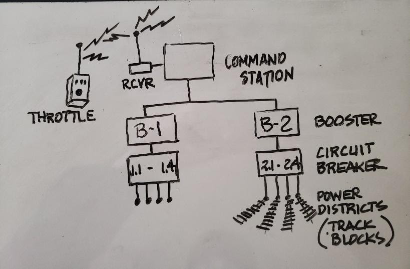
There are two pages that will help in understanding our DCC wiring: 1) A layout track plan labeled CSME as built schematic and 2) A chart labeled CSME Electrical Documentation. (Figures 4 and 5) The track plan uses a legend found on the 2nd page of the CSME Electrical Documentation. This legend indicates place name abbreviations on the track plan and other information. At this time these are working documents and are functional rather than neat and pretty. Some things to know about this documentation:
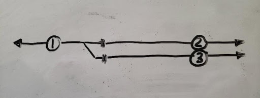
What the heck is an intuitive track block? Let’s take a look at figure 2. Numbers 1,2 and 3 define track blocks. Thick black marks indicate insulated rail gaps. 1 and 2 are mainline blocks and 3 can be a passing track. In terms of operability, a Gene Neville term, an eastbound (L to R) 4 unit set of powered, sound equipped F-7’s rolls thru block 2 followed by 4 powered, sound equipped SD-45’s in block 1. Meanwhile, in block 3 a set of 4 sound equipped, powered F-3’s move a westbound (R-L) train into the clear. In this situation, we could have 12 sound equipped, powered locomotives in these 3 blocks. We want our layout to be able to support this kind of operation. By blocking the track into mainline (1 and 2) and passing track (3) blocks with gaps near the fouling points of the switch, we can split power demands among boosters. The gaps make sense because that’s where trains would stop when given limited authority. This exact situation exists on our layout at the ends of Nashville and Eddyville.
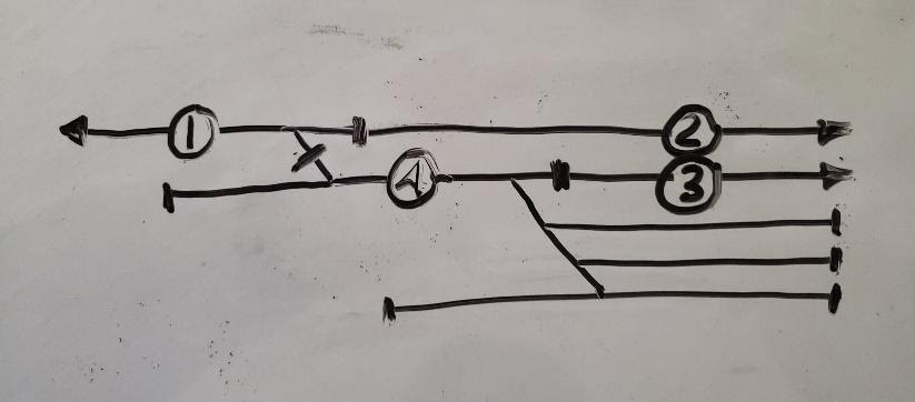
How about something more complicated? Check out figure 3 where we have a figure 2 situation complicated by a yard entrance. We shorten block 3 to stay clear of the yard ladder fouling point and add block 4 to power the yard. In terms of operability we can have 2 eastbound trains on the mainline in blocks 1 and 2, a westbound train easing up to the fouling point in block 3 and a switch engine working the ladder in block 4. If the switch engine or cars stumble on a switch in block 4 causing a short, it doesn’t shut down the mainline (1 & 2) or siding (3). This condition exists, sometimes with a double track mainline with crossovers, at the ends of Philomath, Corvallis and Toledo. Wow! We can see where dynamic balancing can be a bit tricky when we want a layout with prototypical options.
With a bit of study of this narrative, along with the documentation pages mentioned above and noted below in figures 4 and 5, one can go a long way in understanding our DCC wiring system. In addition, Randy, Gene, or myself would be glad to walk you through the system. It is not our aim to make each member a DCC aficionado but rather provide a basic understanding that will enable members to locate problem areas. The documentation package will be available in a binder near the command station when we get up and running. It is our hope that several folks will take an interest in the system and be able to help others keep it running. As old age creeps up on us, it will become more and more important to de-centralize this knowledge.
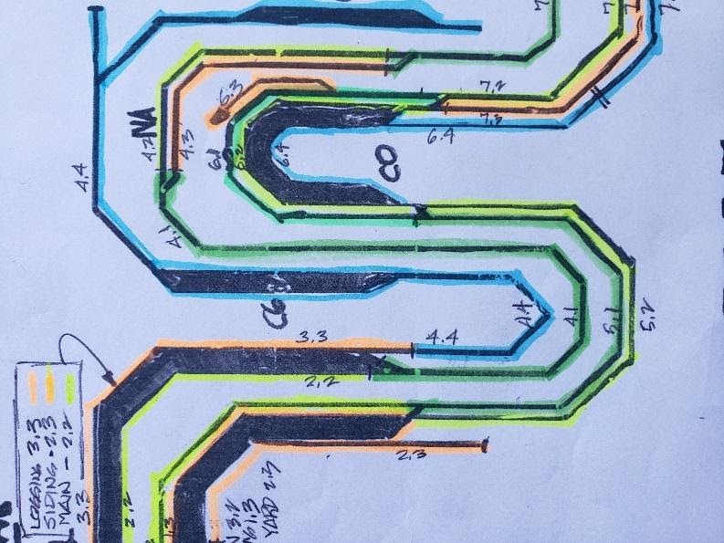
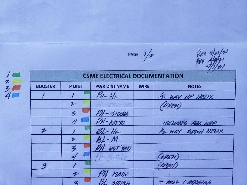
Figure 4 shows a small portion of the power district assignment sheet. This is the peninsula between Philomath (left) and Corvallis (right). Place names and power district assignments are as noted in numbers 2 and 3 above. Colors are explained in number 4 above. Note that lower level tracks are powered by boosters 1, 2, 5, 6 and 7. Upper level tracks are powered by boosters 2, 3, 4, and 7. By spreading the load across multiple boosters and power districts we can accommodate very intense train running . Figure 5 shows a portion of our Electrical Documentation chart. Columns are used as follows: Booster is the booster number, P Dist is the power district number (1 through 4), Pwr Dist Name is the location of the power district using 2 letter abbreviations. When final names are selected for the layout this column can be updated. Wire will be the colors of the wire pairs running from the circuit breaker to the power district. Notes include explanatory notes such as “includes rev. loop”.
It is hoped that interested members can use this documentation to understand the control system and thereby make it more manageable. At a minimum, an engineer can look at a blinking red light, identify the power district number, look it up in the documentation and report it to proper personnel.
4/16/21
Some months back we requested a visit from the fire department and they sent 2 representatives over to have a look at our paper plans on the floor. We asked for suggestions regarding the layout and proposed open houses. Among other things, they advised that we needed a floor length fascia around the south helix. George has been working on the design and fabrication of this part of the fascia. Basic framing for this unique part of our layout was completed this week.
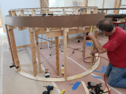
George adds short studs to a custom made base on the south helix for a drop down fascia requested by fire marshals.
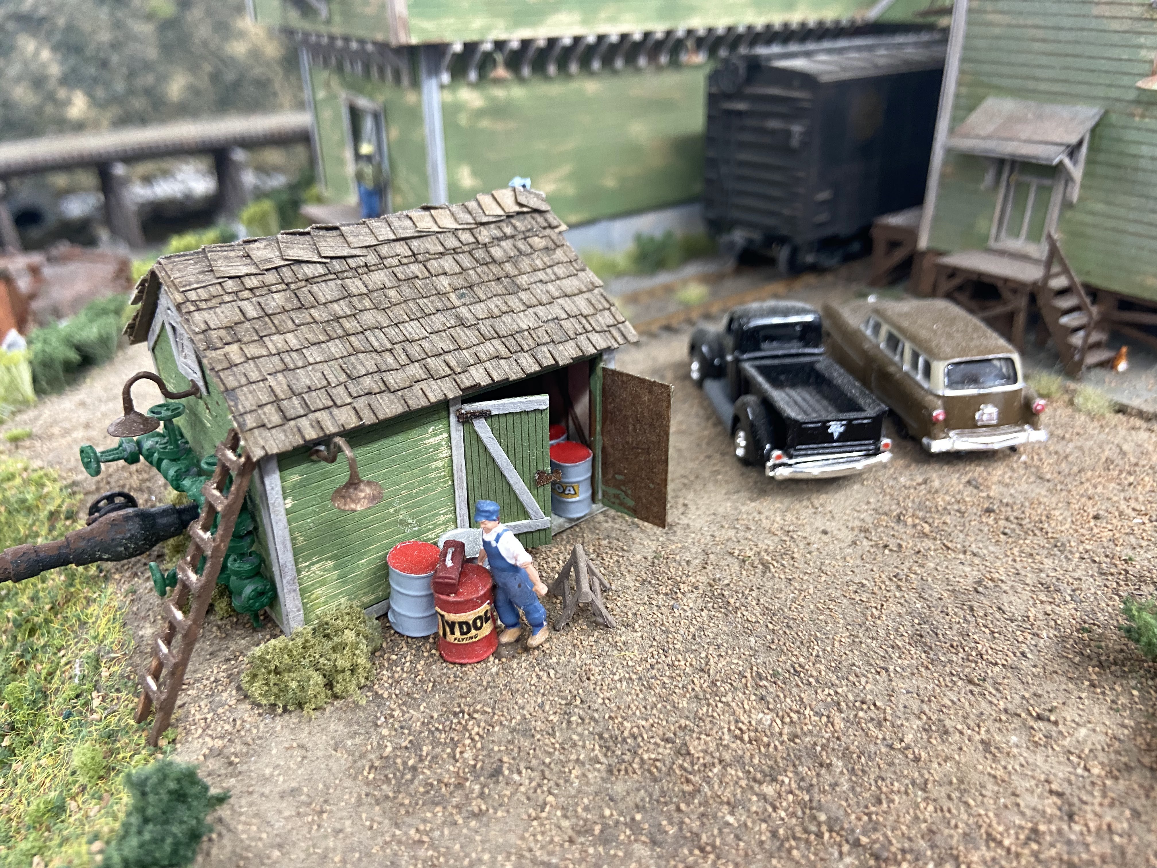
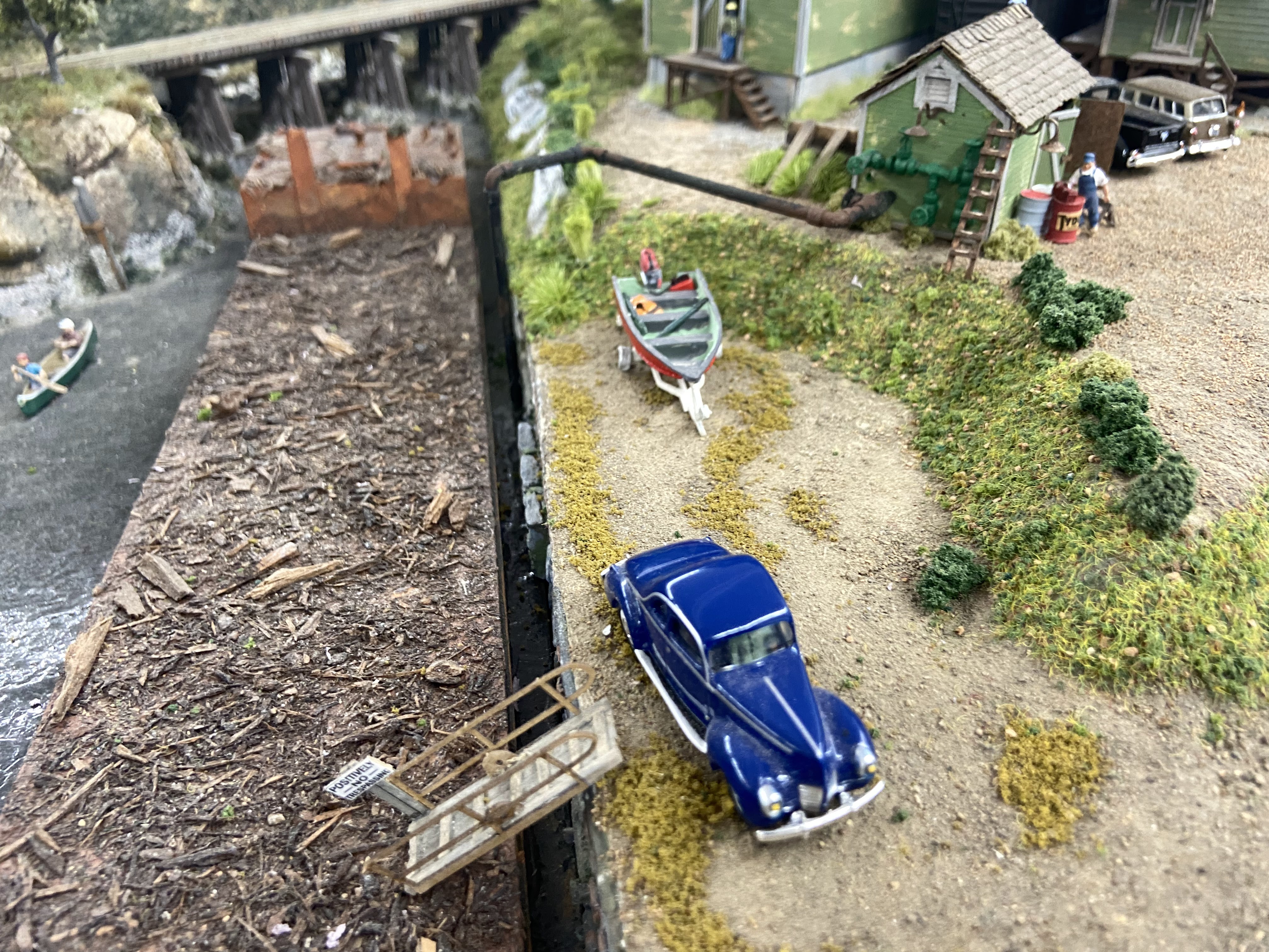
Doug has been working on re-forestation of Eagle Point. He’s also replaced the lighthouse and keeper’s cottage up on the bluff. Scenery in this area will be spectacular as he works his magic.
This construction requires constant sweeping and vacuuming. Bill and Randy have been very diligent in this effort. If anyone wants to come down during off hours and help out, we’d love it. Most of the dust is contained within the cutting room, however some cutting must be done in the main layout room. Any assistance would be much appreciated.
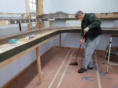
Randy does a classic 2-step with broom. Keeping up with construction mess is a real challenge.
As we near completion of framing and track laying there are many small pieces left over from the old layout. Many of these pieces including “L” girders, track boards with cork and track, short legs, 22,412 lineal feet of used blue and orange #12 stranded wire, and scenery sections are in the new layout room. These serviceable pieces will not be used on the new layout and have been slated for a dump run. Come by in the next week and you can have your choice. They are laying along the east wall awaiting removal. Free to all members. Come and get them. Text or e-mail Jerry, Randy, or Gene if you have questions.
So, what’s up with all the blue tape labels and colored push pins along the track and between rails? Good question. Here are some answers:
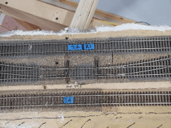
Power districts marked up with tape. Points ofthe left switch are in poor shape and will be repaired. MP 49.2 note is from old layout and holds no authority on new layout.
Blue tape stuck along the right-of-way but NOT between the rails represent feet from our zero point at the door end of the Albany yard. They are placed at 20 foot intervals. It can be thought of as if surveyors started at the UP/SP interchange in Albany and measured west to the end of the line. This was done by Larry and Bill using a measuring wheel. Total length of mainline track on this layout ended up being 452’ – somewhat longer than the 406’ of our previous mainline. We can use these markers, which will be made more permanent and prototypical later, as markers for track and right-of-way work.
Blue tape stuck BETWEEN the rails indicates power districts and booster assignments. 7.4 means booster 7, power district 4. Also 7.2/8.1 means the end of power district 7.2 , rail gap, beginning of 8.1. The heavy bar indicates where the rails should have gaps (offset about 1/4” rail to rail). We expect to have 10 boosters plus a Zephyr, each one having 2-4 power districts powered by a PSX-4 circuit breaker. These power districts are defined by operability (probable number of locomotives within the district) as opposed to location only. Documentation will be thorough and simple. This makes it accessible to interested members for possible trouble shooting.
There needs to be enough power capacity so this layout can be marketed to prospective members as being able to support multiunit operation. This is a first class layout in space, aisle width, mainline length, trackwork, passing track capacity, maximum grade, minimum curve radius and a number of other parameters. We need to have a first class DCC system with sufficient power to support operation, “open house” running, and member needs. This power system will be consistent with those high standards.
Push pins along the track have to do with rail gaps. We will put together a legend for pins, tape, and distance markers so all members can see what’s going on. It will also help us keep track (pun intended) of what we’re doing.
C’mon by and see what’s going on.
4/6/21
Today’s report will be mostly pictures since it’s spring and there’s lots of ranch work to be done. To be sure, progress continues on the layout. Specific scenery details are being added, DCC power districts are being defined and refined, and DCC components are being ID’d so purchases can be authorized. If you visit the club to inspect the work, take note of the blue tape tags with weird numbers on them placed between the rails on some of the track. DON”T Move them. These are power district block indicators for our wiring crew.
Here are some pictures of this week’s work:
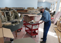
Bill working on Deep Canyon which is in the left side of the picture between the concrete abutments
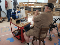
Larry working on the lower level of our helix
using his rolling workbench
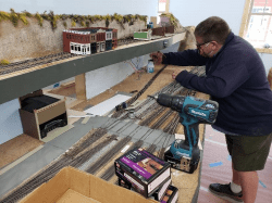
Patrick painting the backdrop for the Corvallis
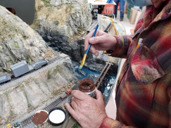
Doug painting “mud” at Eagle Creek
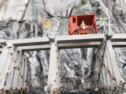
Track foreman Ben Dover ran his Fairmont M-14 out on the
Eagle Point trestle. We have no idea how he got it to curve along the
timbers. Neither do we know who the young lady sitting in the car is?
When asked about the surveyor’s bent rod, he told us it was for laying
out curves.
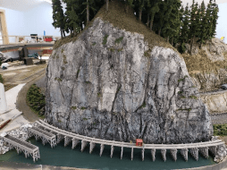
The immensity of the mountainside dwarfs the little
motorcar. Amazing, no ties and no rail, but Ben got his “pop” car out
there.
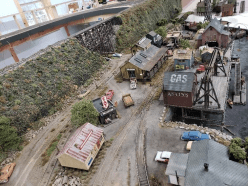
Eagle Cove begins to recover some of its lost detail.
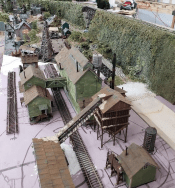
Doug lays out an additional industry
for Eagle Cove
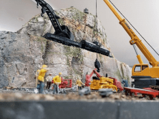
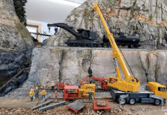
Deep in Eagle Canyon, O’Flarety’s crews get ready for the Golden Spike Ceremony. Track engineer Sureshot Smith pointed out that before we can lay the track, we need the BRIDGE!!
3/31/21
Developing a DCC system for large layouts requires a great deal of thought. Randy, Gene, and myself sat down Monday and Tuesday mornings, put our heads together and developed a plan. This plan was based on maximum operability of the layout or, in other words, the heaviest, best use during an operations session. We wanted to take advantage of the full capabilities of the layout. This included switching in 5 towns, a logging operation, 2 major yards, 2 locomotive facilities, staging capabilities, and several trains on the mainline all at the same time. Actual train crews can number 15 or more with a crew being 1 to 2 people. This is consistent with our minimum 36” radius curves, maximum 1.7% grade, minimum #6 turnouts on the main, 48” wide aisles and long passing sidings. We also had to design in the ability for one or a few persons to come in, turn on the lights and the layout and run a train or switch a few cars.
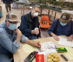
DCC planning session complete with colored diagrams, power district documentation, cookies, french fries and highly motivated participants. Jerry, Randy, and Gene maintain a laser focus on all things Digitrax.
In addition to an operations based plan, we had to develop a wiring system with specific and consistent standards. These standards had to be in as simple a form as possible so members with an interest in layout wiring could understand it, identify boosters, locate power districts and trace circuits. This makes trouble-shooting much easier. Moreover, this same documentation can be used as a guide to actually wire the layout.
The Digitrax DCC system uses wireless throttles that talk to a command station which in turn tells locomotives what to do through a series of boosters, circuit breakers and a wire distribution system. Color coded wires using several colors will be used and copied into the documentation. Booster stations and circuit breakers will be visible and accessible from the aisle thus allowing quick and easy assessment of problems. Our general thoughts were to make the DCC system robust enough to align with the full capabilities designed into the layout, and at the same time, make it user friendly. This work will begin next week and continue for 2-3 weeks.
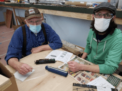
Gene helps Jaymes with a decoder problem in a Missouri Pacific Alco PA
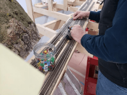
The adept hands of Randy check power district gaps with a “tweeter” and then marks them with push pins. The first time this tweeter went off 3 guys who wear hearing aids grimaced in pain and simultaneously grabbed for volume controls. The piercing sound of this device probably replicates the attack scream of a 25 foot Pterodactyl.
As vaccinations become more widespread, more and more folks are coming by on Mondays and Tuesdays to work, inspect, or just see what’s up. We welcome any who want to visit or work. We always have jobs available. Bill has started working on Deep Canyon scenery. Patrick continues his work on the town in Corvallis. Jaymes came by to get some help with installing a decoder into a really nice MP Alco PA. Larry continues work on the helix “tunnel” liner and ballast. George is making track joints on sidings and Gene continues preparing electrical drops for power districts. Lonnie came by with his famous RS-3 to test the south helix concluding that the new helix allows his engine to pull 19 cars up the hill compared to only 12 on the old layout. Doug continues his work in Eagle Everything and has branched out into marine biology to include menacing sharks, sunken logs, and secretive fish. And then there’s lunch – a time of supreme culinary delights and highly intellectual exchange of thought.
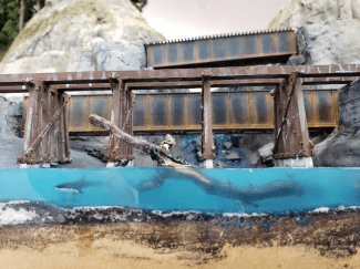
Eagle Creek tumbles into Eagle Cove as this below the bridge aquarium view reveals a lurking shark, sunken log, and other submarine details.
Spring has sprung in the northwest necessitating an increase in ranch work. Spraying fence lines, fertilizing pastures, mowing perimeters, and fixing farm equipment that more resembles yard art or museum antiquities rather than working equipment will make these progress reports shorter and less timely. Oh yeah, and then there’s a mare who is going to foal near the end of the month and, as always, in the middle of the night.
3/26/21
Doug, ever the inventive scenery guy, embarked upon a clandestine mission to pour Woodland Scenics Water Stuff into Eagle Creek and Cove. The pictures speak for themselves. Figure 4, however, is very interesting. It shows liquid-liquid interfaces of 3 liquids of differing densities. The most dense cloudy stuff is on the bottom while the clear, least dense catalyst floats on top. The dye (blue) has a density between the other two and so it sinks thru the first layer and rests on top of the bottom layer. In figure 6 Doug used a stick to pour the stuff so he wouldn’t get bubbles in the water. One bubble did form so he hit it with a propane torch, busted the bubble, lit off the log floating in the “water” and darn near burned up the trestle. It was really fun to watch him dance around on that one but, alas, no pictures. I was too busy ducking and dodging him.
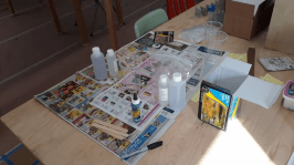
Gathering the stuff
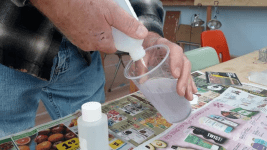
Pouring the stuff

Smelling the stuff
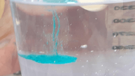
Interesting physics stuff
Doug was so excited about the success of his water pour that we both marveled at it. After about 10 minutes of marveling, Doug realized he hadn’t stuck the trestle, whose piers had to go INTO the water, in place. He managed to get the trestle situated – just barely. We quit marveling and got back to work.
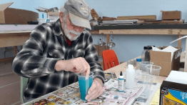
Mixing the stuff
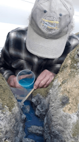
Pouring the stuff
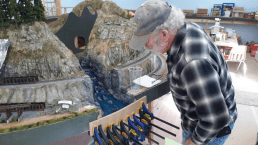
Inspecting the stuff
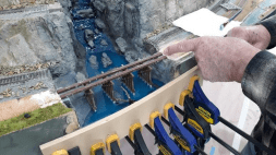
Inserting trestle into the stuff
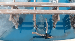
In the last picture, with no caption, look closely into the deeper water and find some fish just above the submerged log and a SHARK bottom center. They don’t need a “no diving from bridge” sign with that guy cruising around. These critters will be visible from the fascia side of the cove not only by looking down into the water but also by looking into it from the side (as if you were swimming in the water—away from the shark). This is sure to be a hit with the public. Good work Doug. Also, thank you Bill and Gene for stopping by to supervise and help.
3/23/21
We would like to thank all of you for your continued support and cheerleading. When a Progress Report is issued and you take time to respond to it, to get in the spirit of the report, to compliment the work and workers, it is noticed. It is also greatly appreciated. It means that someone actually reads this stuff and our work is for a worthy cause.
Comments about progress reports are often discussed during the workday and particularly at lunch. Conversations around the 4’ X 8’, socially distanced, lunch table often times soar to intellectual heights heretofore unknown in the annals of model railroading. Not only are member comments discussed but also details of upcoming work, specific design parameters, sources of materials and methods of construction. Massive amounts of detailed engineering specs are shared and evaluated. And then, after the French fries have disappeared, we resume work or go home to take our naps.
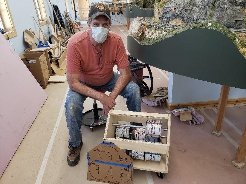
George and his wire caddy
Progress to date has been great. Larry has completed his rock wall tunnel liner around the base of the helix and he is ballasting pre-painted track within the tunnel. Design work has started on the helix fascia including the “windows” to showcase Larry’s work. George is the point person on this. We also ran out of 1/8” Masonite and large pieces of ¾” plywood. This meant off to Home Depot for additional supplies.
Gene reports wire drops are almost complete on the mainline. We used existing drops where possible and then added new ones per Randy’s electrical design specs. Patrick continues working on the Corvallis area and Doug keeps up the effort in Eagle everything. Jaymes J, a new member, came by for a bit on Monday. He’s very interested in all phases of model railroading and wishes to help and learn. Welcome Jaymes. We’ll be happy to provide on the job training.
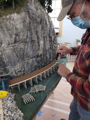
Doug works on the Eagle Point trestle
With framing and mainline trackage about complete, layout construction is ready to move into new phases. We can start thinking about wiring and scenery patches. Wiring will come first and we have been doing some planning and purchasing for that. George made a rolling wire caddy that holds up to 9 500’ spools of 12 gauge stranded wire. We can move it around from booster location to booster location and roll out whatever wire we need. Boosters will be decentralized so they can be installed near the areas they power allowing us to keep our wire runs to less than 30 feet in each direction – 60’ total. There will be 4 power districts per booster each having its own color code. Most wire connections will be made using suitcase connectors – authentic 3M brand rather than cheap knockoffs. Terminations will be made with spade connectors and terminal strips.
Documentation for layout wiring will be designed so all can read and understand it. It will be readily available in the layout room and demonstrations and clinics will be provided for those interested. In this way we hope to have several members able to maintain and trouble shoot the layout electrical system.
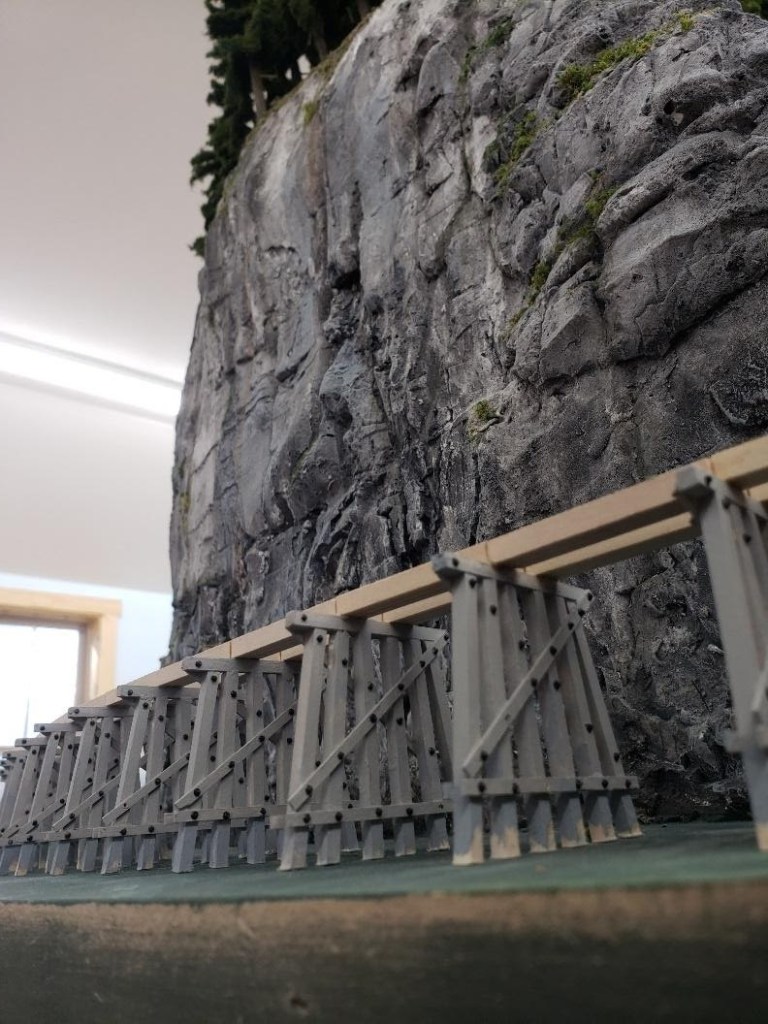
Eagle Point trestle awaiting ties, rail and barnacles
During lunch today Gene brought up the idea of using station names different than actual locations. For example, Eagle Cove is not a real place and therefore buildings and details need not match a prototype. It still looks real but we don’t have comments like “gee, that’s not how I remember it”. It requires new names for Corvallis, Philomath, Blodgett, etc. There probably needs to more discussion among club members. To change or not to change, that is the question. If change is in order, then, to what? Care to provide feedback via e-mails? Let ‘er rip.
3/21/21
Last week was particularly important in regards to several items of interest. First, we actually started running trains – well at least test trains. You can review the previous post for a first hand glimpse of the excitement gripping workers during test runs. These test runs were based on the availability of DCC power on the track. We started at the west end of Philomath (beginning of new helix) and sent power through rails to the top of the helix. This worked out pretty well with the loss of only 1/10th of a volt so we patched up some jumpers to get into Blodgett. That got us clear to the end of Blodgett so another jumper was strung through a hole in the scenery over to a loads in/empties out tunnel portal and twisted together. That got us to the Nashville siding and so on. Amazingly we only had about a ½ volt drop in DCC track voltage with our temporary wiring for 135’ of track.
We also had a “Golden Cork” celebration at 10:30 AM on today. Golden Cork is like a Golden Spike but involving cork roadbed. This means the cork roadbed has been completed for the mainline. Gene, George, and I have been working on this for several weeks. Doug, Larry, Patrick and Lonnie jumped in when we needed help. The Golden Spike ceremony isn’t far off. We just need to turn Doug’s Eagle Creek drawbridge into a fixed deck girder bridge and we’ll have the mainline pretty well finished up. Gene will be cutting in a new switch to the north end staging yard next week.

Golden Cork Documentation
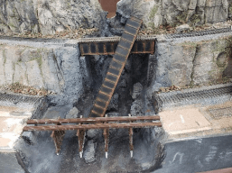
Doug’s Eagle Creek Drawbridge (?)
Larry has been working on a rock liner for the “visible tunnel”. He’s developed a pretty good technique for working in this awkward location. Progress was pretty slow on Monday but by Tuesday he was really cooking. Tinfoil and Sculptamold were flying everywhere. While I was working on the helix track it was necessary to jump out of the way on several occasions.
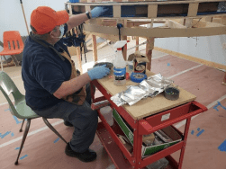
Larry at his “rock tunnel liner” work station
George finished the logging branch from its connection to the main all the way to the camp at the center wall. We might put an extension on it to provide for a longer run-around. There is also an option to tunnel through the wall and run into the north room for another camp.
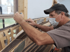
George working on the logging branch.
A fine example of advanced DCC wiring for our test run
Sadly, I must report a significant crime at CSME Tuesday. It involved collusion at the highest level. It was premeditated and, although unproven at this time, clearly conspiratorial. The culprits know who they are. A bit of background is required to acquire a full understanding of this dastardly deed. Laying track on our helix has involved 6’ pieces of flextrack nicely soldered together ahead of time by Gene. I come along and lay 4 or 5 of these pieces on the roadbed, make the required cuts, align the ends and solder them together on the curve. This 24-30’ flex track snake (Snaketrakus atlasii) is then set over to the inside of the curve. Upon signal, the crew takes preassigned stations and I lay a bead of caulk on 24-30’ of roadbed. While the caulk clock is ticking, the crew spreads the caulk, carefully picks up the long piece of flex track WITHOUT kinking it or breaking solder joints, and feeds it to me as I lay it in a smooth curve and subsequently press it into the caulk. Mind you, we do this in very long sections and timing and orchestration are of the essence. It is a well- planned ballet – maybe ballet stretches the point but you get the idea. It results in very smooth curves.
This morning we were orchestrating our ballet. The looooooong flex track had been prepared, the crew was standing by, spreading tools at the ready, and I began laying down the carefully measured bead of caulk. This starts the caulking clock running and no time can be wasted. When I asked for the caulking gun I presumed it would have a full tube of caulk – it did not. Furtive glances among the perpetrators revealed a major crime was beginning to unfold.
Running out of caulk after only 6 feet, realizing that time was of the essence and good adhesion demands wet caulk, I had to get another tube immediately. I was gleefully pointed to an additional tube – carefully staged I’m sure by certain nefarious individuals. I galloped over, grabbed the tube, got it into the gun and began running my bead. I ran out again after only a few feet. Jumping Jerimiah!! Not again!! I knew there were new tubes of caulk clear at the other end of the room – a full 80 feet away. I ran north, got a NEW tube and chugged back south. On my return trip I noticed “the crew” all wearing “cat ate the canary” grins. I accused them rather loudly as they proclaimed innocence. Then they all became “over-occupied” with spreading caulk with heads down but I heard a number of giggles and snickers. I think there may have been a comment about some 75 year old guy galloping up and down the room. We just barely got the track down as they slinked away to their respective work areas. I told them I would report the incident in full detail to the highest authority. This narrative makes said report. They are, even after this, however, a really good crew — rascals every one.
3/16/21
Low Water Hogan, longtime hog head on the SP&S and somewhat famous for being quite the throttle jockey, leaned out of the window of the big 700 and soaked in sounds of staccato exhaust bouncing off cliffs and hills. He had her workin’ hard with full tonnage on the 1.4% grade out of Philomath. He knew full well that a stretch of 1.7% was coming up as soon as he crossed under the high line bridge. Pop Off McGaffe, Low Water’s favorite fireman, was well aware of what the old girl needed and he had the firing valve full open.
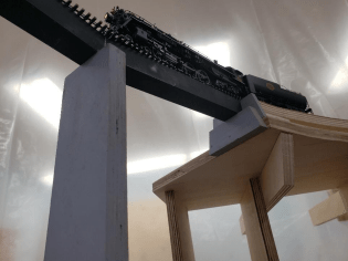
The big S P & S 700, running lite back from Nashville, tip toes out onto the high bridge. This engine is the star of today’s progress report. Thank you George for provide such a fine steed. And thank you to Gene, Larry, Doug, and Lonnie, for helping make this happen.
The endless line of freight cars on the tender hook leaned into the curve behind the engine and tried to hold her back but to no avail. The 8 big drivers dug into the polished steel and kept the whole thing moving. Suddenly Flatwheel Smith, head end brakeman who was hanging out of the gangway watching who knows what, jumped across the deck and grabbed Low Water by the arm. He yelled in the hogger’s ear over the cacophony of big steam sound “Hey, there’s a red flag around the bend!”.
Low Water, knowing full well what stopping on the ruling grade meant, eased off on the throttle and the speed dropped quickly. Pop Off slammed the firing valve almost closed and the stack erupted with clouds of black smoke. Soot rained down on everything. Low Water grabbed the train at about 4 miles an hour so he could stop ½ the distance to any obstruction. Pretty soon they saw it. It was Spiker Mulligan running toward them like a scalded jack rabbit. He grabbed the gangway ladder and jumped into the cab. “Don’t Stop” he yelled. “Keep her at 4 and ease out onto the high bridge”. “My boys found a sun kink in the right rail but we think you can make it across”. “You THINK ” yelled Low Water, “It’s almost a hundred feet down off this thing”. “Yeah, I know,” shouts Mulligan, “but I’m not going to be the guy that has to call a helper out of Philomath for ya”. Low Water nodded acknowledgement and deftly played the throttle and Johnson bar to keep from stalling.
Flatwheel hopped back in the gangway ready to join the birds. Pop Off, eyes bulging, turned around and grabbed the brakeman, jerked him back and pointed down off the engine. Both men latched on to anything steel as the lower loop of the high line passed under the engine and gave way to a yawning chasm of rock and trees. Pop Off got right in Flatwheel’s ear and hollers “it won’t be the fall the kills ya’, it’ll be the sudden stop at the end!” Flatwheel backed up to the center of the cab and breathlessly thanked the fireman.
Mulligan leaned out of the cab as his boys scattered off the tall trestle and he got low on the ladder. Big drivers turned slowly, heavy exhaust churned up the air, black steel glistened in the sunlight and he looked up to give Low Water a slow go ahead signal. The rail mashed against the ties as heavy pilot wheels eased onto the kink. If the big 700 made it all the rest would as well. Everyone in the cab held their breath as they tip toed across the high bridge. Audible sighs of relief filled the cab as the monster engine crossed the deep ravine below and made it to the abutment. The crew gave each other knowing smiles.
This is what mountain railroading is all about. This is what happened after lunch today at CSME. We got a picture of the big 700 as she returned to Philomath on a light engine move. This is not a normal progress report. This is just a short note to let you know that we ran a train from Philomath, thru Blodget and over to Nashville. The wiring we used would make even the finest DCC aficionado blush. George was all smiles as his engine performed flawlessly and 6 grown men almost became emotional.
Have a WordPress.com account? Log in now.

