The High Bridge

3/9/21

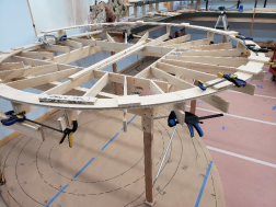
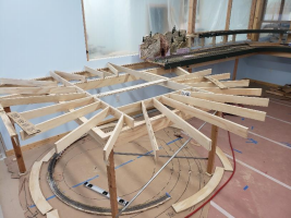
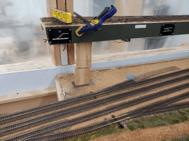
Sometimes we have to engineer parts of the layout on the spot. We call an engineering meeting, evaluate the options, figure in the fix, and get to work. From time to time the fix is complicated enough that a drawing or sketch is in order. An example is where the top of the helix has to cross several tracks far below and, at the same time,  provide abutments for a bridge above. We couldn’t support it on normal risers so we had to use cantilevered stringers to support the sub-roadbed while leaving the lower level mainline untouched. We also wanted scenery  levels to be somewhat below track grade to provide room for a fill. Moreover, this piece provided the transition from the helix to the second level of the layout at Blodgett and vertical accuracy was a must. This required a sketch and some thought. 
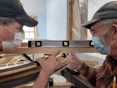
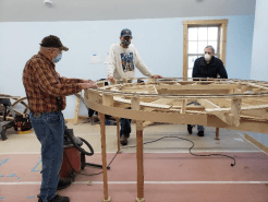
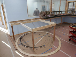
George and Doug celebrate the fact that their construction matches almost exactly the required  elevation of the helix. Right under the level is where the  “high bridge” will go. 
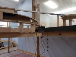
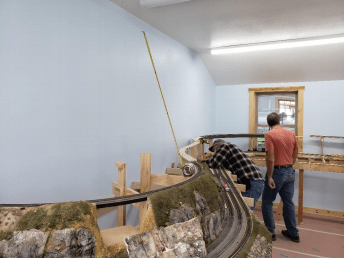
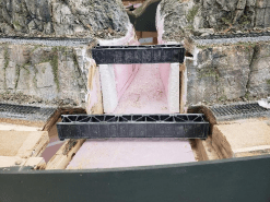
The temporary “high bridge” launches out into  pace, sailing almost 100′ above the valley floor. Hugh donated this 1″ aluminum square tube many  years ago and it’s been waiting all this time for a place to star. Thank you, Hugh.  

Once completed and explained, Doug and George took the sketch and got right to work. They turned it into 3 dimensional reality in record time. As they neared completion, we began checking for level and plumb. This whole process took about 2 hours. As they dialed it in closer and closer, excitement built. We installed the temporary bridge, put a level on it, a nd,  HOTDANG !!, it was dead on. This was the culmination of  about 5 weeks work and will be a focal point for the  railroad. 

The high bridge provides us with some pretty neat things. At 48” (almost 400 HO feet) long and 12” (almost 100 HO feet) high it will be a dramatic scene.  It’s very satisfying to have calculated the helix to crossover itself 3 times, maintain 1.4% and 1.7% grades,  use 48” and 45” radius curves and arrive at precisely the height needed to match the existing height of the upper deck.  It’s close to the edge of the layout and will provide great photo  ops. It has a robust temporary structure so the mainline will operate during the time we take to build an actual bridge.  
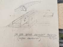
The actual, on site, high quality, fully  dimensioned (with tolerances) sketch from which George and Doug worked their magic

DCC control boxes built by Gene ready for  installation. Also note the backdrop behind the yard being  installed 
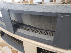
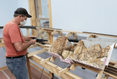
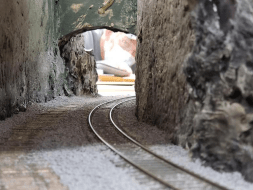
Larry’s prototype tunnel with open front wall, rock backwall, and dark colors to enhance the  “tunnelism”. 

In his own shop, Gene built boxes which will support our DCC system. These boxes are designed to hang below the layout with shelves for booster, power supply, circuit breaker board with 4 breakers, and terminal strips for power districts. The large holes in the sides are for cooling air. They are very nicely built with dadoed and rabbeted joints. As soon as these are installed and bus wires run, trains can go!! 

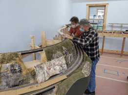
Larry has begun experiments using various rock forming techniques to create a “back wall” to our helix “tunnel”. Right now he’s using Sculptamold layers with crumpled tin foil rock forms pressed into the wet plaster. An India ink wash will be applied to deepen crevasses and dry brushing with light grey will bring out highlights.

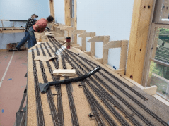
It is our intent to complete track laying on the helix next week. There are long pieces (18’-24’) laying loose on the helix cork right now. If you go by the club  to take a look, please be careful of the temporary track placement and high bridge. 

In general, the work is progressing very nicely and somewhat ahead of schedule. There are many other things happening we don’t have room for (or time to write about) this week – Patrick’s town development, the Eagle Cove barge slip, and an almost finished mainline. 
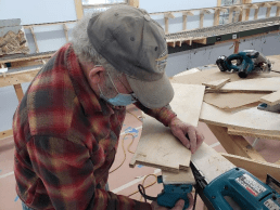
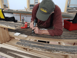
Doug demonstrates complicated and accurate cutting and sanding as he fabricates parts. We haven’t  figured out what this is but it sure looks good.
The Schnabel Test

3/2/21

Gene Neville reports that when we lay in the remaining helix track and he makes a few more patches, the mainline will be complete. That is exciting news. It means we can start running test trains once we stitch the electrical together. Of course, when “test” trains start running, actual “work” slows down considerably.  We all know that “tests” need to be conducted with all kinds of motive power and various train lengths including passenger trains.  In order for these “tests” to be conducted, not only do we need qualified engineers but also many observers for “roll by’s” and detailed track inspections. Moreover, we need to insure that the “tests” can be done over and  over with consistent results. I feel sorry for the poor little ½ mouse power DCC Zephyr power supply and the two number 20 feeders for all 450’ plus mainline. 

Larry Vogt painted the roof of the lower helix level today with black paint and has a great idea for the backdrop along this section of track. It’s supposed to be a rock tunnel that spectators can see into thru openings in the front or outside wall. He’s going to apply Sculptamold to the back wall of the lower loop and press wadded up tinfoil into the wet  goop. When he removes the foil, rock impressions will be left in the wall. Dark grey colorant mixed into the plaster and dry brushed with light grey highlights will create realistic rock coloring. This tunnel will be about 18 feet long, but completely accessible from the outside wall. 

The Sistine Chapel this is not, but we do have our ceiling painted. 

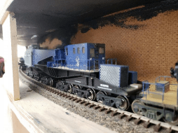
Jerry H’s Schnabel car runs thru the lower level  helix track. Note black ceiling, openings in the tunnel,  and back wall awaiting “rocks”.

Jerry H. came by with a Schnabel car today — about the largest piece of rolling stock we’ll ever see on the layout. This thing has 64  wheels or more. He brought it by for some repair ideas and we confiscated it, put the thing on the track  – that took a bit of doing – and sailed it thru the lower level tunnel of the helix. Clearances were fine and we didn’t knock any parts off the car. Thank you Jerry – also, good to see you up and around. 

George worked with me on finalizing grades on the helix including the upper vertical transition. These grades are very close to those calculated in the beginning – 1.4% for the bottom loops and 1.7% for the top loop. The top loop has a steeper grade because of the smaller radius and subsequent shorter circumference. Please understand that radii of 48” and 45” are very generous in HO scale and grades below 2% are very train friendly. For comparison the old layout helix had a 2.2% ruling grade and 36” radius.  

George successfully stuck this piece of old layout  into the new layout 

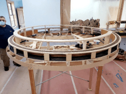
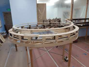
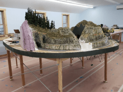
Overall view of helix. Note openings in lower  level “tunnel”. This will have a much more finished look as  we progress. There is well over a scale mile of track in this  structure so we want as much of it visible and accessible as  possible 

We built a vertical transition – easing the grade into level track — about 12” before we get to the bridge. It’s very difficult to build a vertical transition into a bridge structure so we avoided that. Incidentally, this bridge is going to be a little over 4 feet long and about 12” high. In HO scale that’s about 400 feet long and almost 100 feet high. 

Doug is really getting serious about scenery around Eagle Cove, Point, Mountain, Creek, and Canyon. He brought his red scenery wagon over from the old club house along with his personal hobby shop of dirt, rocks, trees, glue as well as other assorted accoutrements with which he works his scenery magic. He also told me of a plan to have fish swimming in his water.  They will be suspended in Eagle Creek and visible from the aisle. Lengthy and detailed discussions will undoubtedly be held at lunchtime regarding the species  and whether they are protected or fair game. 

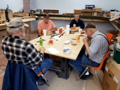
The lunch bunch. Here the free flow of creative  and innovative ideas interspersed with copious amounts of French fries is awe-inspiring.

Scenery

2/23/21

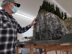
We have some great pictures to share with you in this progress report. Doug, the mayor of Eagle Cove and Grand Poobah of it’s 28 inhabitants, has created his mountain masterpiece for Eagle Point. He has also, unknowingly, re-created a truncated mountain face found several times along the Oregon Coast. That is a mountain, often times over 500 feet high, that meets the ocean at a sharp angle. The wave action over a period of eons wears away the base of the mountain and it starts falling into the ocean. Hard rock like basalt slips off the face in large chunks creating cliffs and softer sedimentary rock just slides down a long slope into the sea. One of these slopes occurs just north of Lincoln City at Roads End Point and is a great source of landscape material for model railroaders. You just can’t take it – legally.

Doug inspects the big cliff at Eagle Point. A long trestle will run along the fascia at the base of this cliff. 

George has been working on the upper level framing, cork and track.  His latest efforts are to create the “S” curve opposite Eagle Point in the north room and inserting some of the more memorable scenery from the old layout into the new layout. The picture below shows a chunk of the old “high line” that he’s going to insert in the upper main across from the roundhouse. He also has his eye on the sidehill trestles that Doug built for the old layout. These will probably fit near the “S” curve. 

George plans the exact placement of a piece of  the old layout

Patrick came by this week and started to plan Corvallis. We will support him by building the basic benchwork and then he will work his downtown magic to create some city scenes. He has some great ideas. I don’t know if they’re classified or not so, in the  future, we may be able to share them with you. In addition to these, he also keeps up with expenditure reimbursements and spending allocations. Thank you Patrick.

Gene continues to work on track joints. He has become best friends with Walther’s code 83 rail joiners. He had a bunch to start with and we ordered 8 more packages of 50 each. That was enough? Nope. He just told me today that he needs 8 more packages!  

The helix as of 2/24/21. Starting from the bottom up: temporary MDF fascia to stabilize the end of stringers, first loop with roadbed and track laid in (this will be  visible as the “inside of a tunnel”; second loop with sub-roadbed only will be scenicked;  third loop mock-up with reduced radius set inside other loops also scenicked. Grades  are 1.4% and 1.6% and radii are 49” and 45” respectively. Reverse loop will be set at  bottom level and hidden like on the old layout. Note BIG BRIDGE mock-up in upper right  hand corner crossing over to Blodget – probably a Micro Engineering tall steel viaduct (any takers??) We should be laying helix track next week.

The Helix

2/10/21

Last report we indicated the helix had been “corked” and rail would go down this week. I’m happy to report that it did. The crew of Doug, George, and Gene, helped me glue down a piece of flex track almost 25 feet long and done all at once! We did this to insure against kinks in the curve. It took some serious preparation and genuine concentration to make it happen but it turned out to be a beautiful 49” radius curve. Moreover, it was on a 1.7% grade and we had to get it right – curve, grade, consistent radius. This curve serves as a base for the rest of the helix and must be pretty accurate. Most of this progress report will be about the process leading to a serviceable helix circle. After setting the sub-roadbed (plywood) and roadbed (cork) we started getting ready to lay in the track. Gene soldered up several sections of flex track 2 pieces long or about 6’. We would need 4 of these long sections plus one 3 foot section. Next, I temporarily laid these long sections of flex-track on the cork and soldered the joints.  After connecting this 25 foot long snake I set it off to the inside of the  curve on the sub-roadbed. The crew was summoned, each given a 6” wide sheetrock paddle and stood at the ready. I shot a 3/8” bead of  Polyseamseal (clear latex caulk) along the inside edge of the cork and we all went to spreading. Short side to side strokes made quick work of the whole circle. Pursuant to my previous instructions, the boys picked up the 25 footer and held it over the cork. I went along laying the track in the center of the cork as the crew fed it to me. In short order it was all down. 

Doug, Gene, and George caulking the helix in preparation for laying in a 25 foot  piece of flex rack. 

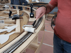
Figure 2 George and his roller. ever in creasing pressure insures that track is im bedded in caulk but not pushed out of  alignment.

Using a small compact mirror (3” x 4” ) I sighted the curve and  all looked well. Next step was a 1” neoprene roller and I lightly rolled  the track. Then George went over it several more times to insure good contact. 

Lonnie came by later that afternoon and we powered this  section of track so he could test it. After some experimentation we found that his engine, a Kato 4 axle RS-3, could pull 16-18 cars up the grade. On the old helix Lonnie reports that it had a 12 car limit. On  this helix the engine did really well except in one location where it routinely stalled. A helix problem had become apparent. 

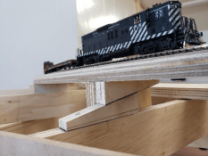
Figure 3 Here is a close-up of a helix ad justment. Note the stringer and riser (just  visible below rear engine truck. In front of  riser is an “adjustable riser” with the diagonal  cut. This allows us to push the sub-roadbed up  in very small increments.  

This morning Doug and I went to the club with another lightweight engine (Athearn GP-7) and tested for consistent operation. We identified the slip out location. We put a  straightedge across the plywood and found it to be a bit low causing a hump in another place – right where the engines stalled.  Before checking the actual grade in this location we re-leveled the  “L” girders using levelling screws in the bottom of the legs. This further defined the problem area in the sub-roadbed. Releasing the screws from the sub-roadbed into the top of the riser, allowed the plywood to adjust itself. It also caused another problem area.  We adjusted both areas (see figures) and re-tested with a train. 

Now folks, it’s been 5 months or more since we ran a train on the club layout. I tested the helix several times and then Doug wanted to re-test it – several times. About then Gene came by and he wanted to re-re-test the helix – several times. That poor old  Athearn GP-7 went up and down that curve many times as we  “confirmed” test results. I’d say that curve has been thoroughly tested. In fact, we tested it to full locomotive slip-out – quite a few times. Those wheels were SHINEY!  Not only did we have glistening wheels but the code 83  (.083 high) rail is now probably about code 79 (.079). In other news, Doug and George re-set the grade into Eddyville. After a bunch of hard work they have all of the mainline sub-roadbed installed in the north room! 

George’s Gorge

2/3/21

The first loop of the helix has been “corked” and track is due to go down next week. This will be about 25 feet long and we’d like to test it. We want to hook up a Zephyr (Digitrax)  power supply to the rails and have some of you come by and try it out. The idea is to see how many cars certain engines will pull up this 1.7% grade on a 49” radius. It is still possible to recalculate and reset this grade, although it would be a major pain. The idea of the test is to see if it’s something we can live  with. We will report test results in one of the next progress reports. We’ll let you know when it’s ready for testing and particulars about how to do it. 

Gene, John and Randy kibitz over the newly corked helix. 

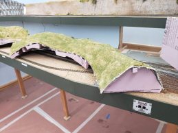
As framing began for the mainline above the old Albany Yard (Diesel facility) we came up with a plan to cantilever the stringers over the main level. This will create a second deck and provides support for a single track mainline and separate logging line above. Stringers are angled downward in front to define an embankment which can then be “rocked” to create a right of way built on a fill over natural rocks and hills. This second deck also provides for more room behind first level main lines for streets, buildings and (?). 

Doug and George align framing for the second deck above Albany yard. Angled stringers will provide for enhanced scenery potential.

An exciting development happened today as we unveiled the beginnings of a spectacular geological formation known as “George’s Gorge”. It will be found across the aisle from Eagle Point and runs for 15-20 feet.  This amazing piece of model railroading extravaganza will include scenery extending from knee level up to head high and above. The crossovers at old Asher will cling to the side of a mountain while the “hi-line” will snake through  several curves as it traverses the rocky crags above. Side hill trestles, a tunnel or two, and certainly a rock shed will punctuate this bit of scenic delight. Close access will make  this a photographer’s delight and kids will remember watching trains over their heads for years to come. How did this concept come about? Well, it all started with George standing on a ladder confirming track alignment. Then he and Doug, always politically correct, summoned me AFTER lunch to answer an engineering question regarding the “S” curves. As we concocted one theory after another and attempted to rationalize what the two of them had done, ideas began to flow. Gene joined the conversation and creative juices really erupted – mostly it was hamburger grease from lunch.  One thing led to another and a conceptual landform emerged that would make any self-respecting  geologist cringe. We concluded that a master’s thesis could be written about our ideas and they would involve bending the tenants of geomorphology to the  max, but we could make it work. Thus began George’s Gorge. Stay tuned for additional details. 

Doug and George team up on the “S” curves through George’s Gorge 

Possible scenic contours are developed with a tape measure near the “S” curves. The cliffs could actually be this high . . . we’ll  see.

The Robe and Chariot Guy

1/27/21

This week we worked on additional rail joints, Eagle Point, and adding sub-roadbed to the helix. The Whistle Stop delivered on time and under budget with 8 packages (384) of Walther’s code 83 rail joiners for about 1/3 the cost of what we expected. Great deal? Well, not necessarily. They have changed vendors and the current code 83  joiners are very much simplified but still serviceable. Gene,  the rail joiner guy, says the jury is still out. He’s used several of them and they work but he has yet to render a final decision. We’ll keep you posted on his deliberations. 

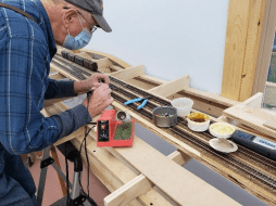
Gene meticulously solders rail joints. He tried blowing the solder fumes away from his face with the mask on but it didn’t work

Doug continues work on Eagle Point and has defined the mountain with pink foam and roughed in the canyon with Sculptamold. rock castings have been laid out and he is deciding upon what type of geologic stratigraphy he wants to incorporate into this yawning  chasm. His concept of superposition, faulting, synclines and anticlines will impress even the non-rock hounds.  Believe me, graduate students in geology at OSU will have a field day trying to explain all this. Our railroad  traverses some amazing landforms and Doug will make them even more spectacular. 

Eagle Point begins to take shape. The pink foam and white canyon are where the geology lesson will take place.

We occasionally pull Doug off his scenic endeavors and make him work on the more mundane aspects of layout building such as sub-roadbed. Last week we completed the radial framing to support our helix and this week we glued up and set the first sub-roadbed circle. It is big – about 8’ in diameter. This is what we need to get our 1.7% grade and 12 ½” rise. We used pocket screws and Titebond II glue to glue up sub-roadbed on Monday and Tuesday we started setting the grade. 

Some of us in our golden years can remember the TV series Welcome Back Kotter – the story of an obstreperous kid who came back to his old school as a teacher. His numerous sins were revisited upon him.  Kotter can’t hold a candle to the CSME construction crew I work with. To wit: The construction of a helix has,  by its very nature, some math involved in its assembly.  So my teacher juices started to flow and I asked George and Doug if they wanted me to share some of the math with them or just hand them the screwdrivers and  drills and have at it? Doug immediately wanted the drill. Before handing him the tool, I gave a very brief  review of radius, diameter, circumference and the concept of Pi. I advised them that we were going to set this grade mathematically and also check it with a level. I  figured it would help to have a common vocabulary other than profanity.   Doug said “I know all about that stuff, let’s get to work “. “Really”, sez I. “Yup, you know that guy Pith-a GOR-us”, sez Doug. I sez, “that sounds like a dinosaur”.  Then I asked “you know about Pith-A-gorus?” Doug sez,  “yeah, y’know, he’s really old, always wears a robe and rides around in a chariot”. I sez, “Pythagoras has to do with right triangles, although it does relate to a thing called a unit circle”. Doug sez, “Hand me the drill”. I got him back at lunch.

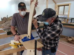
George and Doug drill pocket holes in roadbed using Gene’s Kregg Drilling fixture and guide. 

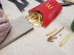
Some “cork fries” were added to Doug’s lunch but he caught them before they went down. 

The first turn of the new helix in place and at grade. Note the difference in size when compared with the old helix as drawn on the paper below. This baby is big but it reduces the grade,  increases the radius, offsets the top loop, includes a reverse loop,  stays out of the hallway, and is mostly visible track. We’ve accommodated most of the design parameters requested by club  members.

After all that, we got to work marking off linear measurements of circumference at each stringer around the first circle. Then we multiplied that run in inches times the rise per inch (.0177”) and added the height of the stringer (2.875”). That gave us the total length of riser required at that point. We called out the numbers to George, he accurately cut the risers and we clamped  each one to its respective stringer. After we had the base circle set (and ran out of clamps) we used the grade tool to check the grade. We also calculated  total circumference and then compared that number to our physical measurements. George and Doug had built the circle so accurately that we were only off by about ½%.  

Next week we’ll screw this whole assembly (sub roadbed-risers-stringers) together and begin to lay in the middle level. This will be a much easier task because all we do is use match cut blocking to raise the middle level straight up from the bottom level. The off-set top level will have its own risers and by then George and Doug will be “helix masters”. I’ll just sit back, relax, and watch them put the old guy with the robe and chariot to work.

Gene Gets Serious

1/13/21

BIG news today – Gene is back at work and he started putting the actual track together. He’s already got the mainlines hooked up through the yard and is moving west. He’ll be laying cork and flex track. For being this soon after knee surgery he’s doing really well – I’ll bet he won’t tell his doc what he’s doing. 

Doug starts painting the fascia

On Monday we engineered access to the HVAC wall mounted unit in the south room. We landed a peninsula directly under the unit so that the opposing curves form a “Y” against the wall providing an access. This will be hidden with removable foam blocks of scenery. We’ll provide the foam blocks, club members can invent the scenery when the time comes. George and Doug continue to be . . . well . . . . George and Doug. I think we should video some of their antics and offer DVD’s for sale. Doug got loose with a paint roller and can of paint around noon, and not to be out done, George grabbed a roller as well. Within about 40 minutes we had a new coat of primer on the whole lower fascia of the layout. During lunch George decided to institute and new quality control program for the layout as seen in the picture below.

 George’s new quality control program

At close of business today, we had all of the lower level sub-roadbed done and the upper sub-roadbed complete in the south room – Philomath and Corvallis plus 2 blobs. This does not include the helix. The upper level, as I have indicated, can be a challenge to support in some places, however an interesting and highly effective process has developed. I plan the layout pieces or new plywood sub-roadbed as required. I cut and fit it where needed. George comes along and cuts risers, shelf  brackets and gusset plates. Then Doug comes over and helps George set the grade or level as required and they screw it all together.  

Gene gets serious about track joints. This one is on the double track main through Toledo yard.  Double track hanging in the air to the left is part of  Eddyville and track in immediate foreground is Eagle Cove extension going to the paper mill 

Gene was putting in some time today on rail joints and I happened by. Shortly thereafter Lonnie showed up and was waiting for Randy and John.

 Doug checking out his abandoned track in the Eagle Point tunnel. 

Bridges and Helix Stringers

1/21/21

Doug continues to work on Eagle Everything (Cove, Canyon, Tunnel, Mountain). His latest projects are the bridges over Eagle Canyon. We all know Doug doesn’t do anything half way and this is no exception.  Bridges can be made very simply by gluing Micro Engineering bridge girders to the plywood sub roadbed and you have a ballasted deck girder bridge. Not Doug.  He has to hack out the whole track, ties, cork, and plywood structure and replace it with a see-through, lacy,  super-detailed, deck truss bridge complete with  abutments with forming lumber lines and all. It will be a  showpiece with not 1 bridge but 2 bridges and a trestle.  Big time open house photo location here.  He also showed us a sneak preview of some mill structures he’s working on at home. When it’s rainy  outside he can’t wreck RC airplanes so he works on  building kits. These are very high quality, meticulously  weathered and super-detailed. Can’t wait to see them in  place. 

Doug’s handy work included here so you can say you saw it when it first started

Gene is working away on stitching up our mainline. This week he worked himself right out of rail joiners. He got as far west as Ashar (sp) and had to quit. The Whistle Stop hobby shop in Portland is coming to our rescue with 8 packs of Walther’s Code 83 rail joiners. Thank you John. These are pricey little rascals, even with a discount, but hold rails in  alignment very well and make great expansion joints. 

Helix L girders in place. The large circle is  the 49″ radius outside curve. The inside curve  approximates the reverse loop 

George continues to be our framing guy. For 2 days he chased me around with a screw gun and so we started the helix construction. We have been asked to reduce the grade of the helix and that’s been done. Instead of a 2% grade with a short section of  2.1% it will now be 1.7% throughout. In order to do this we had to increase the radius to 49”. We had  several considerations when arriving at this radius measurement: 1) upper to lower grade difference of  about 12.5 “, 2) reversal of helix direction because our room width was reduced by almost 5 feet which shortened up Philomath and it’s western approach,  3) a location for the reverse loop with a minimum radius of 30”, and 4) the Fire Marshal’s “request”  that we not encroach on the hallway to the door. We  have accommodated these issues with a really nice design that minimizes hidden trackage and allows for easy access. It will also provide for a “peek inside the  tunnel” view. 

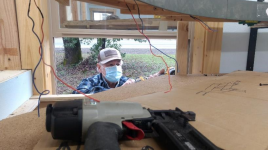
George traced out patterns for the helix parts. Gene and Doug worked in Gene’s shop to cut out all the  parts. Helix L girders were put in place Monday and we started framing the helix base Tuesday. Today – Wednesday – the base was pretty much completed with a finish nailer. Doug and George will screw all the  parts together next week. 

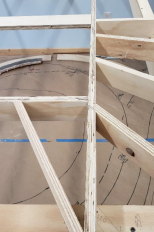
Radial stringers are in place atop the L  girders. Note the square access hole in the middle  (piece across the access area is a temporary center point). Some of these stringers are cantilevered quite a bit, however, a stout fascia will  provide support.

We have reached a few milestones. We can now take out the rest of the paper plan that documented the original layout as it has served its purpose. We just installed the last L girders for the  helix – no more L girders. We have only 3 or 4 more lower level stringers to install and those will be complete. Well done, crew. Until next week. 


Radial stringers require angled  joints

Upper Level Work Begins

1/5/21

The CSME work crew for this week was Doug, George, J erry AND John stopped by as well as Gene. John has taken point on the bathroom fan and trim finishing projects. That’s great. Gene said he had gotten “really bored” at home and needed some of the Doug and George show – he got it. He also brought lunch so he can come back anytime.  He says he wants to start on track laying.  That’s a good thing. 

We began work on the upper level moving from south to north or from Blodgett to Nashville. Some of the framing for the new Blodgett area became quite creative since we had no wall for attachment and had to do it with cantilevers, brackets and posts – none of which will get in the way of operation in Philomath.

George went after the last two chunks of old layout and produced some useable scenery sections, stringer and riser stock, and trackboards – plywood, cork, and flextrack.  Some of this material is available to club members for free. For example, we have about 90 lineal feet of “L” girders that are not pretty but certainly serviceable. They are laying under  Philomath in a bundle – come and get them but put back what you don’t want. Also, the scenery hills with a foam/screen substrate are pretty stout and can certainly be moved, cut and fitted, and installed on a new layout. They are sitting in Corvallis. This foam/screen  technology was imported to the club by Larry Vogt and it’s too bad we can’t use them in the new layout. The major rock casting walls want to stay at the clubhouse for a bit since we  may be able to fit those into place.

Some of our framing had to be done from  outside. Neither rain nor snow nor cold nor  salamanders nor tree frogs can deter our intrepid  workers. “Model Railroading is fun”. 

Doug is still working on Eagle Cove and Eagle Point. He’s laying the groundwork (pun intended) for some more of his famous “arte de ferrocarril”. We’re all looking forward to what he has in mind. He put a new blade in his oscillating saw and now he’s like a wild man. He already chopped a big hole in his old scenery and claims he’s going to put  bridges across the chasm. He says he likes the new blade because the old one was so dull it made a lot of smoke – it did! 

A typical scenery section carefully excised by George. These are available to club members on a first come first served basis and the cost is minimal — $0.

Upper Level Bracketry

12/30/20

The City Administrator of Adair Village stopped by the new club on 12/29/20. He was most impressed with the progress on our layout.

This additional 2020 post references the construction of the upper deck. We share this progress report in hope that it may come in handy on home layouts.  

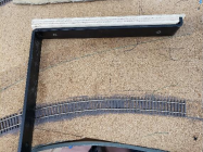
We will be using heavy shelf brackets in some areas of the upper level. They are metal  and our layout is framed with plywood – how to make the connection AND keep a fairly exact dimension is the problem. We will do this in two steps. First we apply a wooden plate to the  bracket as shown in figure 1. Notice that it has a rabbet and chamfer to clear the upturned end of  the bracket. Second we set the bracket about 1/8” low and shim up to the proper level, figure 2.

Figure 1: Wooden plate screwed to heavy metal bracket 

Often times when supporting the upper level we have trouble cutting risers to the exact dimension we need. This is when we use a temporary adjustable riser. These are fairly simple as seen in figure 3. We make a 10 degree diagonal cut across the riser (dark line) and then slide the joint up or down as required. This  allows us to frame to a pretty exact  dimension. Once we’ve hit this dimension we clamp and screw  pieces together. Alternately we can  leave the temporary riser in place, mark the slip joint with a vertical line, apply Titebond 2 glue to the slip faces, match the lines and secure with an air powered finish nailer. As we connect new sub roadbed to existing sub-roadbed,  making sure joints are straight and strong can be a challenge. We will be using ¾” plywood gusset plates below the sub-roadbed joints. They  will lap as much as 8-12” on either side of the joint and be glued and screwed for strength. Figure 4.  

Figure 2: Bracket in place, notice shims

Figure 3:Temporary riser. This is the Blodgett piece above Philomath about where the old rock shed was on the high line. 

Figure 4: Gusset plate extends out to the right just  behind the clamp. Temporary riser is used to support  plate while we run the screws in. Switch control panel  is for the logging line crossover in Blodgett.